Continue to Site

Eng-Tips is the largest engineering community on the Internet

Intelligent Work Forums for Engineering Professionals

  • Congratulations KootK on being selected by the Eng-Tips community for having the most helpful posts in the forums last week. Way to Go!

Amp rating of current meters 2

Status
Not open for further replies.

Mbrooke

Electrical
Nov 12, 2012
2,546
Do analog amp meters have a current limitation?

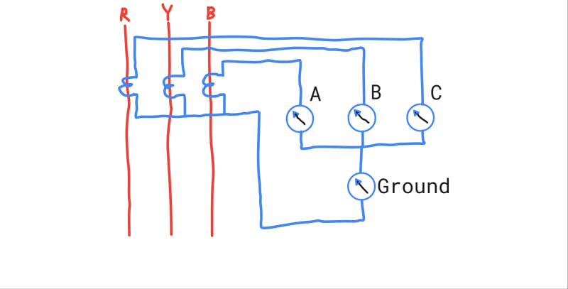
Basically I want to monitor leakage current on a 3 wire system. A, B, C meters 0-2000 amps, Ground meter 0-30 amps, possibly 0-5 amps range.

Question is, what if I get a persistent ground fault over 30 amps? Will my meter burn up? How will the burden of each meter effect the others under normal and GF conditions?


autodraw_8_12_2020_qvh6o9.jpg
 
Replies continue below

Recommended for you

Often metering CT's were utilized which saturate at a relatively low value, above nominal. That protects the meter from burning up.

Nearly every amp meter I've seen in a substation is 0-5 A sec. Our local disco would often put a meter in series with relay CT's, but I've noticed that even the peak demand readings are about 1/5th of the meter full scale reading. Most times the normal load current is barely readable. I will use my own ammeter with a stab to get a reading if I need it. I've never found a burnt up meter, but these are feeder breakers at a sub (phase & gnd feeder protection).
 
Good to know- which leads me to another question. For this application would I use metering CTs or protection CTs?
 
I would say that depends on a number of things. Do you have existing CT's available? Installing CT's is no small issue and they aren't necessarily inexpensive. Is this a permanent or temporary install? What kind of resolution are you looking for? Are you in a control building or outside somewhere?

If, for example, you are in a control building and have say a SEL-351, it has 4 current inputs that you can wire it up to exactly how you have drawn above. You could even connect a Zero Sequence CT to the 4th current input if you wanted. IIRC SEL can take 20A continuous on its current channels, may 15A on 500 series. Ebay is your friend in this case. I just got a SEL-451 for $200 for a 61850 lab.
 
These are purely panel mounted current meters on the main gear of a building.

I can get any CT of my choosing.

 
If you use self contained meters, the current rating is the primary test current.
A meter for a 100 Amp service will appear to be be rated at 15 Amps.
That is the main test current, the meter will be used for 100 Amp services.
The meter used for 200 Amp services will be rated at 30 Amps test Amps.

Bill
--------------------
"Why not the best?"
Jimmy Carter
 
@waross I'm confused what you mean by this?

I'm thinking 2000:5 CTs.
 
OK, CT feeding an analogue meter.
At some current the meter will burn up.
We don't know at what current.
I have heard of a protection for over current of ammeters but have not tried it.
The voltage drop across an ammeter is very little.
I have heard suggestions that back to back diodes connected across the meter terminals will start to bypass and limit the maximum voltage and thus the maximum current through the meter.
If it takes more than 0.7 volts to drive the meter full scale, use two or more diodes in series for each string.
Disclaimer. I have not used this technique myself.
If I had occasion to use it I would check the calibration and effectiveness before putting it into service.

Bill
--------------------
"Why not the best?"
Jimmy Carter
 
Local disco? "Stayin' alive, stayin' alive..." [2thumbsup]

CR

"As iron sharpens iron, so one person sharpens another." [Proverbs 27:17, NIV]
 
Dear Mr. Mbrooke

Q1. Do analog amp meters have a current limitation?
A1. Yes. Reference IEC 60051, or latest for detail.
In brief, requires over-current factor:
a) up to 1.20 times for 2h for all accuracy class,
b) 2 times for 0.5s for Class 0.5 or less,
c) 10 times for 0.5s for Class 1 accuracy and above,
Caution: Over-current than above or longer duration may damage the meter.
Q2. Basically I want to monitor leakage current on a 3 wire system. A, B, C meters 0-2000 amps, Ground meter 0-30 amps, possibly 0-5 amps range. For this application would I use metering CTs or protection CTs?
A2. Reference IEC 60044-1, or latest for detail.
a) You may use a measuring CT 2000/5 A or 1 A, alternatively a 2500/5 or 1A; Class 1 or 3. These CTs would saturate >2 times. Refrain from using [protection] CT, as it would be more costly and higher chances of damaging the meters during short-circuit.
b) A,B,C ammeters 0-2kA for 2000/x CT or 0-2.5kA for 2500/x CT,
c) ammeter for ground-fault 0-30A or 0-60A.
Q3. "... what if I get a persistent ground fault over 30 amps? Will my meter burn up?"
A3. See above A1. a) a 0-30A ammeter shall be able to withstand at 1.2x30A for 2h. If you use a 0-30A [long range 240 deg] moving-coil ammeter, you should be able to read as low as 5A.
BTW: a) a [moving-iron 90deg] meter would not give good resolution at very low end,
b) If it is observed that persistent > 1.2 x 30A, a 0-60A meter may be selected,
c) for a 2kA system, a persistent ground-fault > 1.2 x 30A is NOT acceptable!
Q4. How will the burden of each meter effect the others under normal and GF conditions?
A4. With a 2000/5A or 1A measurement Class 1 or 3 CT, the burden would be >5VA. The meter burden would have no problem for a CT having burden >5VA.
BTW It is important to earth the CTs. It shall be earthed at [one point] only.
Che Kuan Yau (Singapore)
 
I must admit I can't think of a single application where I'd actively choose analogue panel meters over some recording instrument. From what I've seen, even lower end multiple function meters cost about the same as 3 analogue panel meters. There's definitely the application where its better to have a moving gauge rather than a discrete numerical display, but there are also options to cater for that.

Is this a permanent measurement? I'm assuming that the CTs are for higher than LV applications, otherwise a Rogowski based test set would likely be able to pick up the leakage current without having to worry so much about the CT ratio inaccuracy issues, saturation or damaging the meter. Even so there may be an option for it that might provide the results you're after.

EDMS Australia
 
Thanks che12345. What about IEEE meters?


Freddy yes this is a permanent install. 240 volt 3 wire system. 2000:5 CTs.

Can you tell me more about Rogowski based test sets?


The idea here is to pickup low level ground faults.

Before anyone brings up GFP main breakers remember that on generator power tripping GFP is not required.
 
CR-

I can almost hear that falsetto of Barry Gibb.

Disco=Distribution Company, Transco=Transmission Company & Genco...

In my neck of the woods, Joint Use Sub Stations have a line of demarcation on the single line and switching diagrams, using the abbreviations mentioned above. I think I'm transported back to 1976 when I see this as well. Many of the younger guys have no idea why I'm singing the Bee Gees and think I'm nuts.

On an unrelated note, I've been hearing an interview on the radio with the guys from the band U2. They are proclaiming the Bee Gees to be just as good as the Beatles. U2 noted that it took many years to appreciate the quality of the music because of the obvious anti disco feelings many had in the 1970s and 80s.
 
I believe the metering security factor is an IEC thing. My company here in ANSI land commonly puts non-revenue meters on protection CTs without suffering any problem but reduced accuracy. In some cases our CTs are dual rated for both protection and metering.
 
Dear Mr. Mbrooke

Q1. "... What about IEEE meters?"
A1. I do not have any IEEE standards on meters, as the IEEE standards are not widely used in Singapore; where IEC prevails.
Q2. "..Can you tell me more about Rogowski based test sets?"
A2. Mr. FreddyNurk would have more detail. It is a "portable meter" NOT intended as a [permanent] installation. It works with [its matching meter]. The price would be far more than {3CT + 4 meters}!.
A2.1. What I know about Rogowski coil is used with the portable test set as you have mentioned. Check out all major portable testing instrument manufacturers, they include Rogowski coil for measuring current only. The sensor consists of an [air-cored coil]. It does NOT saturate and is linear over the entire measuring range. It can be manufactured as a small diameter [flexible band] of rather long length, able to go around big/small diameters. It works on an entirely different principle; different from the usual clamp-on ammeter (invariable with an iron core), similar to a standard iron-core CT.
Q3. " The idea here is to pickup low level ground faults".
A3. A 0-30A [long range 240 deg] moving-coil ammeter, should be able to read as low as 5A.

@Mr. stevenal
Q4."... My company here in ANSI land commonly puts non-revenue meters on protection CTs without suffering any problem but reduced accuracy. In some cases our CTs are dual rated for both protection and metering".
A4. There are significant difference between IEC and ANSI CT standards including their application. Be aware of " non-revenue meters " and " without suffering any problem but reduced accuracy "
Che Kuan Yau (Singapore)
 
If your intention is to pick up low level ground faults then use the equipment designed for such a purpose, i.e. protection CTs and relay.
If it was a one off verification then Rogowski based kit would do the job (i.e. Fluke Power Meters, Scopemeters and so on often get optioned with them). They do also exist for permanently installed protection applications, although I admit I've not seen them at LV.

Of course, US grounding schemes notwithstanding, its also possible to use a single zero-sequence CT appropriately positioned to do what you've stated.
There's also the consideration that you'd need to use maximum demand or similar panel meters unless you intend to stand in front of it all day.

EDMS Australia
 
Dear Mr. FreddyNurk

F1. "...If your intention is to pick up low level ground faults then use the equipment designed for such a purpose, i.e. protection CTs and relay."
C1. I take it that the proposed circuitry is to "monitor" the [phase current and observe the corresponding earth-fault current], or to "detect" which [branch feeder or load] that causes (high earth-fault current). If this is the case, a [measuring CT] should be selected instead of a [protection CT]. A measuring CT would have a better accuracy up to 1.2 x the rating. As it is NOT intended to "monitor" any current higher than 1.2 times.
F2. "... its also possible to use a single zero-sequence CT appropriately positioned to do what you've stated ...".
C2. Yes. A zero-sequence CT to house 3x2000A conductors would be a very "huge" (usually) rectangular metallic frame which involved cost and installation room. The proposed circuitry is minima, which serves the intention of "monitoring".
F3. "...There's also the consideration that you'd need to use maximum demand or similar panel meters unless you intend to stand in front of it all day."
C3. No. I take it that the circuitry is intended to "monitor" the running current and "observe" the corresponding earth-fault current. The running current and earth-leakage current taken at the same time at say 15min interval over a 8h working cycle would give a good "trending indication". It may help to pint-point which feeder or load is the [culprit] that causes the "high" [earth-fault current].
A maximum demand meter with usually 15min time lag, which pushes the pointer to the maximum position does not indicate the "trending" between the [load current and the leakage current]; at any particular time/load cycle.
Che Kuan Yau (Singapore)


.
 
During a fault, I don't see why your ground meter would be any more likely to burn up then your phase meters.

Is this a resistance grounded system? If not, I don't see why you expect there to be low level ground faults. Any ground fault usually transition to a full-on failure rather quickly.

I would like to see a link to a 2000:5 metering CT that would saturate at a low enough current to avoid damaging a panel meter that is limited to handling say 10A maximum.
 
Dear Mr. LionelHutz

Q1. "...During a fault, I don't see why your ground meter would be any more likely to burn up then your phase meters".
A1. If a measuring CT is used, both the phase and the ground meters SHOULD remain [intact] under any level of short-circuit current. However, if a protection CT is used, damage (may) result.
Q2. "...Is this a resistance grounded system? If not, I don't see why you expect there to be low level ground faults. Any ground fault usually transition to a full-on failure rather quickly.
A2. Mr. Mbrooke clarified that it is a Solidly grounded wye.
In a LV 2000A system, there will [always/persistently] be say up to 5% of leakage current. They do NOT "transition to a full-on failure rather quickly", at all.
e.g. say there are 10 x 200A feeders. Each 200A feeder having a [persistent] earth-leakage current of say 3A, which is realistic and no cause of alarm or to trip it off. For a total of 10 branches, the total leakage current would add up to 30A. This can be that each feeder may have say 10 x 10A loads, where each " healthy" load having persistent some 100s mA leakage current of various degree.
Q3. "...I would like to see a link to a 2000:5 metering CT that would saturate at a low enough current to avoid damaging a panel meter that is limited to handling say 10A maximum".
A3. Reference IEC 60044-1, or latest for detail.
Per above IEC Standard for Measuring CT, in brief:
a) for Accuracy class 1.0 : +- 1.0% [current ratio error] at 100% of (rated primary current). With +- 1.0% [current ratio error] at 120% of (rated primary current). Observation: commencement of [saturation] i.e. when the primary is increased to say 10x2kA=20kA, the CT output SHALL maintain at +- 1.0% [current ratio error] ,
b) for Accuracy class 3.0 , --- % current ratio error at 100% of rated primary current. With +- 3.0% [current ratio error] at 120% of rated primary current.
Che Kuan Yau (Singapore)


Status
Not open for further replies.

Part and Inventory Search

Sponsor