Continue to Site

Eng-Tips is the largest engineering community on the Internet

Intelligent Work Forums for Engineering Professionals

  • Congratulations IDS on being selected by the Eng-Tips community for having the most helpful posts in the forums last week. Way to Go!

different deflection is obtained when the moment of inertia is identical 3

Status
Not open for further replies.

Kai Wang

Structural
Mar 5, 2020
12
Hi all,

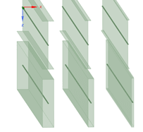
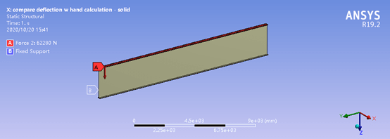
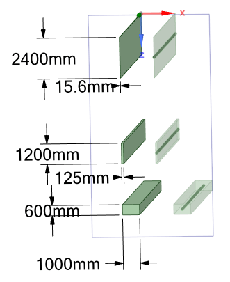
Does anyone know why different deflection is obtained when the moment of inertia is identical? The following beam and solid all have the same moment of inertia along the global X axis. The load is a uniformly force on top of each model and all 6 DOFs of all the beams are constrained at both ends (for solid the 3 translational DOFs are constrained.)

The max. deflection w/ hand calculation is 0.152 mm which is very close to the model w/ cross section of width=1000mm and height of 600mm.

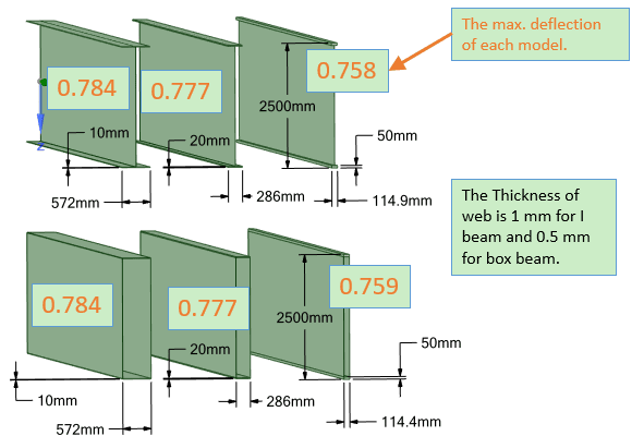
The web of I beam and box beam is very thin, i.e. 1 mm.

Thanks in advance!
solid_beam_tnjxno.png


result_of_solid_beam_ahh2ro.png


I_beam_and_box_beam_c7x1je.png


result_of_I_beam_and_box_beam_ycnhjr.png


load_and_boundary_condition_b7sfbw.png
 
Replies continue below

Recommended for you

Futher explanations are as follows.

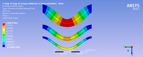
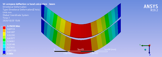
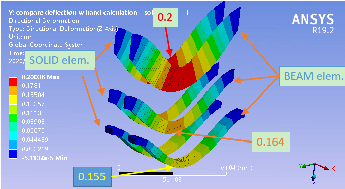
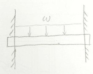
In above figures, the second one is the results of the first one, i.e. the results of solid beams. The fourth is the results of the third, i.e.the I beams and box beams. The fifth shows a scheme of the load and boundary condition.

The hand-calculating equation used to compare with the FEA is (1/384)*(w*L^4)/(E*I) since these are beams restrained at both two ends.
 
Were these simulations linear or nonlinear ? Which type of beam elements was used ?

Can you provide just the value of maximum deflection for each case (for example write it next to its scheme in the first and third image) ? What is the trend in these results - thin walled beams deflected more ? Is it true also for analyses carried out with beam elements ?
 
Per beam theory, the deflection consists of two components - bending and shear. The equation, Δ = 5wl4/384EI is the bending component, you need to include shear deformation in the calculation, though it is usually negligibly small, except for deep beams.
 
"all 6 DOFs of all the beams are constrained at both ends (for solid the 3 translational DOFs are constrained.)"

so you're over constraining the beam, and have to include that in your hand calcs. The beam is more than a double cantilever … you're also constrained the axial freedom.
I would fine tune your constraints to give a simply supported beam.

I'd be interested to compare the solid beam (3D elements) with a 2D beam with the same cross section … I bet that's not the same result.

maybe repost in either the FEA forum or the ANSYS forum ?

are you saying that the rectangular beam deflects 0.2" and the I beam (with the very thin web) deflects 0.7" ? … probably shear deflections
what does your hand calc say ?

another day in paradise, or is paradise one day closer ?
 
Honestly, I don't think we know enough about how the two beams are modeled to answer very well.

That being said, I have some ideas:
1) If you used solid elements then you have to mesh them through the vertical axis for them to provide accurate results.
2) Someone suggested that shear deformation could be the source. That is also valid because the I beam has a very thin web and more shear deformation should occur.
3) Someone else mentioned end conditions. When I look at your deflected shape, the first beam resembles a beam with fixed / fixed supports and the 2nd one looks like it has pinned/pinned supports.
 
Thank the answers from all of you! Sorry for my original ambiguous description.

I guess r13’s reply just answer my problem, i.e. I should include shear deformation in the hand calculation. Previously I do not know this. I will learn the Timoshenko beam theory to try to compare with FEA result again.

A further question: actually, what I want to know is the deflection of a space steel frame which is built by welding many steel tubes. Its global shape is prismatic and composed of longitudinal girder, lateral vertical column, transverse beam, and diagonal brace. It is put horizontally with support at every several meters, maybe can be called continuous beam. Vertical load is applied on it uniformly. I want to estimate its deflection in span under gravity.

The method I tried in my previous post is to sum the cross area of the upper longitudinal girders as well as the lower ones, assign these cross areas to the upper and lower flanges of I beam or box beam which has the same height with the space frame. Then calculate the deflection with beam theory. I am not sure if this is an appropriate method. Since my knowledge on mechanics is limited, may I ask what the proper method is on this subject?

A brief explanation on your questions are as follows.

Figure 1
result_of_solid_beam_-_2_jxeqqh.png


Figure 2
dim_and_result_of_I_beam_and_box_beam_aalfo3.png


The max. deflection by hand calculation is 0.152 mm with the equation of (1/384)*(w*L^4)/(E*I).

The analysis is linear and the large deflection option is off. The beam element is BEAM188 in ANSYS.

What I want to model is just the fixed-fixed beam as the figure below. Therefore, for model with BEAM element all 6 DOFs at both ends are constrained while for model with SOLID element the 3 translational DOFs of the both end faces are constrained.

fixed-fixed_beam_ayrs8m.png


As JoshPlumSE said, I also feel strange why the results of I beam and box beam behaves like pined-pined beam although they are constrained in the same way as that of the solid beam, i.e. the 1st and 2nd figures in original post.

The deflection in previous post is magnified for showing the deflection mode clearly.

The deflections of the same shape with SOLID or BEAM element are the same as one can see from the color in Figure 1 of this post. This is also true for the I beam since one I beam was analysed with very fine SOLID element.

Thank you!
 
For the I-Beam/box beam, are you restraining one point at each end, or the whole section? If just one point the beam ends can still rotate. The beam plates can bend within the member and let go of the moment, leaving you with quasi-pin.
 
@ Tomfh

When modeling with BEAM element, the 3 rotational DOFs as well as the 3 translational DOFs of both ends are constrained. The same constraining method is used when modeling solid beam with BEAM element. But as you can see the solid beam shows fixed-fixed while the I beam and box beam seems pin-pin. I do not know the reason.
 
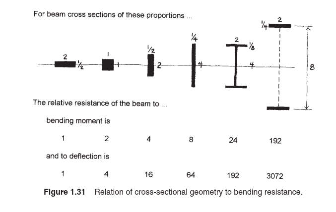
a bit off topic ... excerpt from : "simplified mechanics and strength of materials" - James Ambrose - 6th edition

bending_deflection_kqrkhl.jpg
 
is that right ? that a beam with a higher I has a higher deflection ?? can't be !

or is it saying that the beam has I 4* and deflection is 1/16* ?? if so, an odd way to express it … IMHO.

another day in paradise, or is paradise one day closer ?
 
One of the keys to the pinned vs fixed deflected shape may be the end restraints. Member, that when using solid elements to model a pinned beam that ONLY the joints at the centroid of the beam should be restrained. If you restrain the joints at the flanges, then you are created a fixed supported instead of the desired pinned.
 
yes, instead of constraining each node, make a RBE spider and constrain the single central node.

another day in paradise, or is paradise one day closer ?
 
To start with, your assumption that the MOI for those shapes are equal is not correct. Close to each other and exactly equal are not the same thing.

You need to recalculate- significant figures matter.
 
Status
Not open for further replies.

Part and Inventory Search

Sponsor