Eng-Tips is the largest engineering community on the Internet

Intelligent Work Forums for Engineering Professionals

  • Congratulations waross on being selected by the Eng-Tips community for having the most helpful posts in the forums last week. Way to Go!

Positional tolerance applied on elongated holes (round ended slots)

Status
Not open for further replies.

Burunduk

Mechanical
May 2, 2019
2,335
IL
Consider fig. 7-34 of Y14.5-2009 or 10-35 of Y14.5-2018.

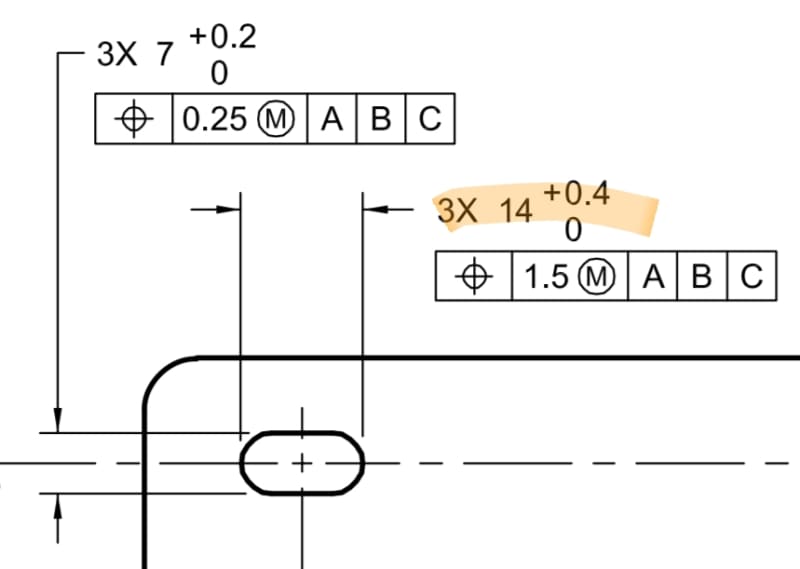
My first question is - would you say that the position tolerance applied on the 14mm length of slot dimension could be interpretable/inspectable if the position tolerance was applied at RFS, or handled according to the center plane interpretation of MMC?

And the second question is, how would you construct the MMC boundary had the end radii of the slot weren't tangent to the horizontal parallel surfaces and dimensioned by directly toleranced radii? For example 6X R8+/-0.2
 
Replies continue below

Recommended for you

My personal opinion on both - I wouldn't.

I see Y14.5 interpretation of slot position as sort of exception. Normally the non-feature of size should be treated with combination of Profile and Position as on Y14.5-2009 Fig.8-24.

But then with some assumptions, like slot is intended for loose fit with the fastener, hence MMC, the ends of a slot are not really relevant, hence only full radius slots are considered, etc., etc. we come to simplified solution, which only benefit is consistency - I believe this interpretation goes as far back as 1966 standard.

If "slot" in question was somehow important and required precision fit, I wouldn't even use Fig. 7-34 approach.

Once again - it's only my personal opinion.

"For every expert there is an equal and opposite expert"
Arthur C. Clarke Profiles of the future

 
Burunduk,

Why would I apply an RFS tolerance to those slots? Slots like that probably are a keep[‑]out to clear screws, as CheckerHater notes.

The radii at the ends of the slots are controlled by Rule[ ]#1. Why would you apply a tolerance to them?L How would you measure them? Why would you care?

--
JHG
 
The radii at the ends of the slots are controlled by Rule #1
I would gently disagree with this statement.


John-Paul Belanger
Certified Sr. GD&T Professional
Geometric Learning Systems
 
drawoh said:
The radii at the ends of the slots are controlled by Rule #1

Belanger said:
I would gently disagree with this statement

Interesting question though: Do opposing radii constitute a feature of size?

Draw1_qduonv.jpg


"For every expert there is an equal and opposite expert"
Arthur C. Clarke Profiles of the future
 
drawoh,
I am asking about a slot but actually, I am interested generally in the application of position on features of similar shape. For example, rather than a slot, it could have been an external feature such as a tab with rounded ends, that assembles into a slot-shaped pocket in a mating part. Position at MMC on the length dimensions on both parts could be considered to protect boundaries that ensure the ability to assemble and provide additional tolerance for departure from MMC. The standard shows the boundary/surface interpretation but if hard gaging is not desired, I guess someone may think of applying the center plane interpretation, to inspect with CMM.

CheckerHater,
As I see it, the elements between which the toleranced dimension is given could be considered "a set of two opposed parallel elements ... which is associated with a directly toleranced dimension". That is part of the definition of a Regular FOS. Those are parallel line elements to be specific.

It could also be classified as "a directly toleranced feature or collection of features that may contain or be contained by an actual mating envelope that is a sphere, cylinder, or pair of parallel planes".

So that is already two different options that perhaps support the classification of a feature of this shape and dimensioning as some type of FOS. Where am I wrong?

With that said I'm somewhat concerned with how an unrelated AME may behave for this kind of feature.
 
Yes, it's an interesting question... I have to noodle it some more :)

Essentially, the radii are not "directly toleranced."

John-Paul Belanger
Certified Sr. GD&T Professional
Geometric Learning Systems
 
Belanger said:
Essentially, the radii are not "directly toleranced."

Could you clarify why not?
14mm is directly toleranced and it is what I consider to be a size dimension with which the position tolerance is associated.

Screenshot_20201030-084806_Drive_dptotf.jpg
 
The statement I was challenging is that the radii are directly toleranced.
Do you see a tolerance upon the 6X R?

The dimension that you highlighted does not impact the form of the radii. It's just the distance between two arc tangents.

John-Paul Belanger
Certified Sr. GD&T Professional
Geometric Learning Systems
 
Belanger,
I agree that the value of the radii is not directly toleranced (or dimensioned) in this case. But the requirement for a regular feature of size is that it is "associated with a directly toleranced dimension". Aren't the ends of the slot and the 14mm dimension associated with each other? And again, the feature of size in question could be not the complete radii but "two opposed parallel (line) elements".

Also, as I alluded to in my second question, with a slightly different shape the value of the radii could be directly toleranced. Example:

Screenshot_20201030-171219_Drive_srpqjg.jpg


The two 10mm radii could be specified with +/- tolerance. But even if the radii were basic and controlled by profile they could still be considered as "a directly toleranced feature or collection of features".
 
Let's back up... The idea being discussed for now is whether Rule #1 applies to control the form of the rounded radii. And we know that Rule #1 only applies for a regular FOS. So in the pictures being presented (2009's Figure 7-34 or your Figure 1-30), are the rounded ends considered a regular FOS?

There seem to be two tolerances involved: the radius and the distance across the slot:
The radius -- even if toleranced -- is not a regular FOS (no opposing elements).
The distance across might be a regular FOS, but that doesn't control the form of the radii because it's just speaking to the tangent points.

It seems that you're trying to combine those two ideas in order to call the radii a regular FOS. That's where I would disagree.

John-Paul Belanger
Certified Sr. GD&T Professional
Geometric Learning Systems
 
Belanger,

In Burunduk's figure, the radii have a radius dimension, and position. If the radii are nominally flush with the sides, only the total length is required. How would you control the radii specified as per 7[‑]34 of Y14.5[‑]2009 or 10[‑]35 of Y14.5[‑]2018? You specify slots like this as keep[‑]outs for screws.

--
JHG
 
Belanger, I never suggested that each radius separately is a regular feature of size. I suggested that the length of the slot (the distance across the slot as you call it) may be considered a regular (or irregular) feature of size - and per your last reply, I suppose that you agree ("The distance across might be a regular FOS"). If it's a regular FOS (which I think is supported by the wording of the definition in the standard), then rule #1 applies to it. The way I would interpret the rule #1 requirement for the slots in fig. 7-34 of Y14.5-2009 or 10-35 of Y14.5-2018, is an envelope of two parallel planes 14 mm apart, fitted inside the slot. The requirement is met if a condition is achieved where both of the extremities of the slot which are specified with the dimension 14+0.4/0 are simultaneously outside of the space that is captured between those parallel planes.
 
I said that the distance across might indeed be a regular FOS, but does it really control the form? How can you control the form of two points??
So I still disagree about lumping the FOS (of the distance across) together with the radius and saying that it controls form.

I don't have a great answer to the question -- I'm just expressing my hesitancy about throwing Rule #1 into the discussion.

John-Paul Belanger
Certified Sr. GD&T Professional
Geometric Learning Systems
 
Belanger,
For what it's worth, I'm also not crazy about rule #1 being thrown into this discussion since the original questions were about the application of positional tolerances, and rule #1 is not a substitute for a position control or for a direct tolerance on the radii value when the ends of a slot are not fully rounded but partially rounded.

But since the topic was already introduced and is being discussed - I do think that rule #1 as a form control is potentially applicable. You ask "How can you control the form of two points??" - well, actually in terms of the 3D geometry those are not two points but two nominally parallel line elements. So if the nominal shape/form is two parallel lines, arguably rule #1 permits imperfection of straightness and mutual orientation of these line elements and hence imperfection of the form of the feature comprised of them, limited according to the amount of departure from the 14mm MMC limit imposed by the 14+0.4/0 dimension. The two line elements can be curved, have irregularities, or non-parallel as long as the 14mm boundary is not violated and the actual local size doesn't exceed 14.4.
 
Status
Not open for further replies.

Part and Inventory Search

Sponsor

Back
Top