Continue to Site

Eng-Tips is the largest engineering community on the Internet

Intelligent Work Forums for Engineering Professionals

  • Congratulations waross on being selected by the Eng-Tips community for having the most helpful posts in the forums last week. Way to Go!

Reinforcing angles to WT 2

Status
Not open for further replies.

BAGW

Structural
Jul 15, 2015
388
Hi,

I am reinforcing WT with an angle. I am trying to understand how to come up with the force for weld design between the angle and the WT.

Was planning to design the shear stress as "Shear x (Area of angle) x (max Y1 or Y2) / (Moment of inertia of composite section)".
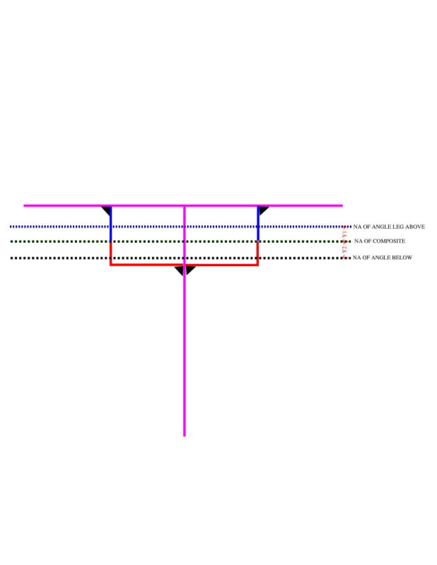
Document1_kmcd6p.jpg
 
Replies continue below

Recommended for you

Yes, the equation is f = VQ/I. Where f is shear flow (demand), Q = the first moment of the portion of the area (above/beside the plane where the shear flow is being calculated) about the neutral axis, and I is the moment of inertia of the composite section.
 
Unfortunately, these multi-cellular shear flow problems are quite complex. If you're interested in the theory, start with this recent thread: Link

Without explicitly considering shear stiffness, I feel that all that can be said of your scenario is this:

1) There are three paths (vertical webs webs) available to connect the compression and tension regions of the composite beam.

2) The aggregate shear demand in the three paths must equal the total shear demand on the composite section.

3) By way of symmetry, the leftmost and rightmost paths must carry equal shear.

Unfortunately, that leaves us still not quite knowing how much shear goes through each path. Were I in your shoes and not looking to earn a PhD for this effort, I would conservatively simplify the problem to that shown below to get the weld sizes. Usually the demands on these welds are pretty minimal and the conservatism won't hurt the economy of your design meaningfully.

C01_bsgglh.jpg
 
I suppose this would be better although it's hard to imagine the difference would amount to much.

C01_go1r23.jpg
 
Agreed. I was planning to use the angle webs only for sizing of the weld shear.

If I use the area of the angle and the max of "Y" as mentioned above to get the moment area (Q), that should suffice correct? Do I need to do anything with the web/flange of WT for moment area calculations?
 
Use flange of the T for sizing the top welds; and use the stem below the top of the angle leg for the lower welds.
 
The approach suggested by r13 in his last post is what I had in mind in my first sketch as well.
 
Status
Not open for further replies.

Part and Inventory Search

Sponsor