Eng-Tips is the largest engineering community on the Internet

Intelligent Work Forums for Engineering Professionals

  • Congratulations waross on being selected by the Eng-Tips community for having the most helpful posts in the forums last week. Way to Go!

Shear Resistance of L-Shaped Column

Status
Not open for further replies.

efFeb

Structural
Dec 25, 2019
65
CA
Good Afternoon,
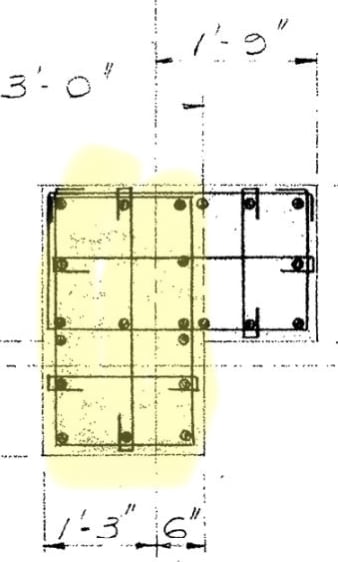
I am doing some checks for shear strength of columns in an existing building and have come across several L-shaped columns. I can think that I could check these like i might check shear strength of an L-Shaped beam, but this would end up being very conservative, and I need my values to be fairly accurate. Does anyone have any resources or thoughts on an approach to calculating shear strength of a column like this?
Thank you so much for your time!
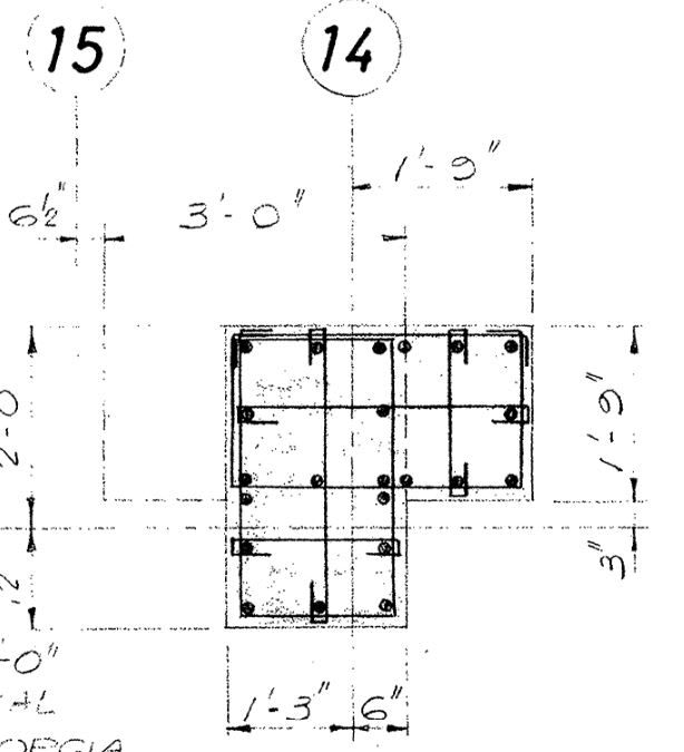
col._l_shaped_yllrxd.jpg
 
Replies continue below

Recommended for you

I would have ignored the L shape and just consider the 'web'. Also, I might only consider 2 of those vertical legs properly anchored, depending on what code you're going off. The one on the far left with the 90 degree cogs probably does provide a fair amount of shear strength but relying on it would be questionable.
 
I would say the original designer had considered this as two rectangular columns to resist forces in two directions. If you know the design loads at that time, you can perform analysis, get reactions, and back check its strength to confirm the design assumption.
 
Here’s my column for shear in one direction, and vice versa in the other. Designers back then would likely have done similar.

E9892348-FA69-4EB8-84B8-9242F683814F_dy66hw.jpg
 
At ultimate limit state, you should be able to add the capacity of the deeper and shallower parts as though they were separate members, subject to being consistent with the split of moment and shear between the two parts.
 
steve49 said:
At ultimate limit state, you should be able to add the capacity of the deeper and shallower parts as though they were separate members, subject to being consistent with the split of moment and shear between the two parts.

Generally yes but...

1) I view the rational splitting of shear and moment between the two parts for the purpose of shear capacity evaluation to be a pretty much intractable problem and;

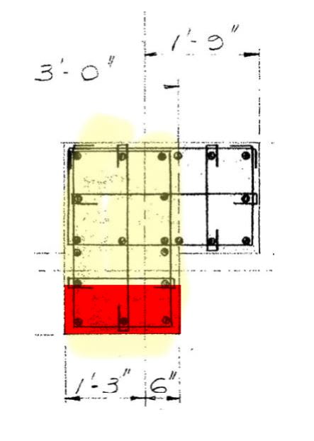
2) I would expect the capacity to be very much dependent on the direction of loading. For the compression block shown below, I'd expect the parts of the cross section outside of the web to be of marginal benefit given that a disproportionate share of the shear resistance comes from the compression zone.

C01_f47zzy.jpg
 
IMO, the approach for T-beam design is applicable for this case - general shear resisted by the web in direction of load. The entire cross section can/shall be considered effective to resist torsional shear.
 
Kootk said:
1) I view the rational splitting of shear and moment between the two parts for the purpose of shear capacity evaluation to be a pretty much intractable problem and;

Would it be conservative to just add the two parts separately? Moment and shear capacity of deep rectangle plus moment and shear capacity of small rectangle?
 
Tomfh said:
Would it be conservative to just add the two parts separately? Moment and shear capacity of deep rectangle plus moment and shear capacity of small rectangle?

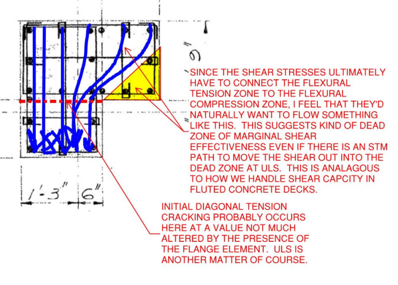
I don't feel that would be a conservative approach for shear capacity where the flange element would be in flexural tension. My understanding of our code shear capacity provisions is that they take account of the beneficial impact of having part of the cross section in compression or, at the least, not in tension. I don't believe that the flange element would have such a compression zone when resisting a flexural demand that would put the flange in tension. As such, while the flange element no doubt contributes something to shear capacity:

1) I don't know how to quantify that and;

2) I'm confident that the contribution would be less than our usual shear capacity checks would suggest.

Expressed more pedantically, I'm not sure what "dv" ought to be for a flange element that is nowhere free of flexural tension.

In addition to the stuff mentioned above, I submit the mechanics of materials analysis shown below for the consideration of any interested parties. Obviously, initial diagonal tension cracking usually occurs in combination with a flexural crack.

C01_fdxglz.jpg
 
I found this thread searching for something else and remembered I wanted to reply but didn’t get around to drawing the necessary pictures. It may have been reckless to say that you can just add the big rectangle and small rectangle as though they were separate columns as I can’t prove it; just relying on the idea that a composite structure should be as strong as the sum of its parts. I’m always looking to learn about exceptions though and wanted to prompt the discussion that was developing.

In this post, when I refer to an axis I mean a geometric axis. I don’t think the principal axes of the gross section are too relevant after cracking and due to the stirrup orientation. I’m also ignoring any shear lag as the outstand is quite stocky. And referring to the posted geometry in particular as trying to cover all possible shapes and reinforcement layouts would be next to impossible.

First off, this (correct) principle: “a disproportionate share of the shear resistance comes from the compression zone [KootK]”. If we compare the single-rectangle simplification to the L-shape reality, the L-shape has ~double the reinforcement so ~double the compression zone. This doesn’t double the shear capacity but, for this geometry, adding in the small rectangle would only increase the shear capacity by ~40% at a guess (depending on which code you work to). That’s not too far off what you would get based on the increased reinforcement quantity applied just to the larger rectangle.

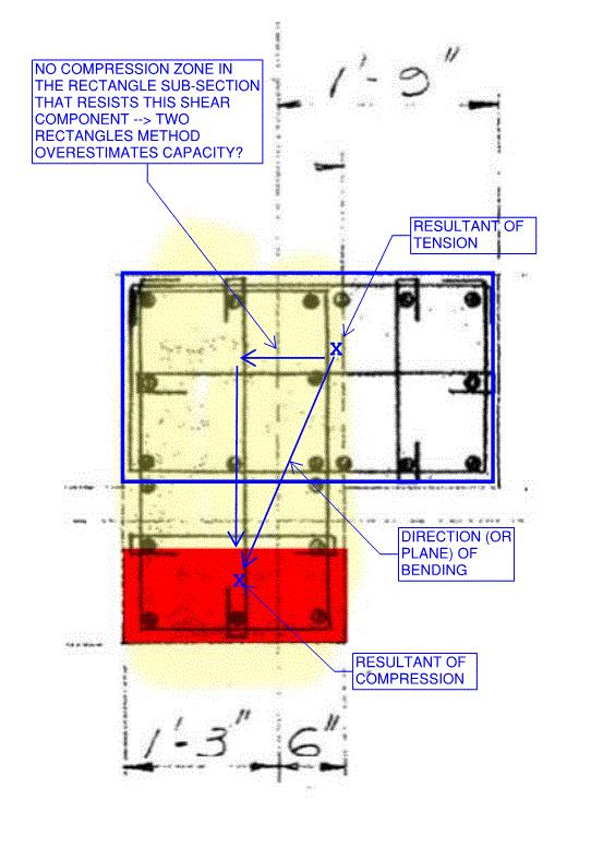
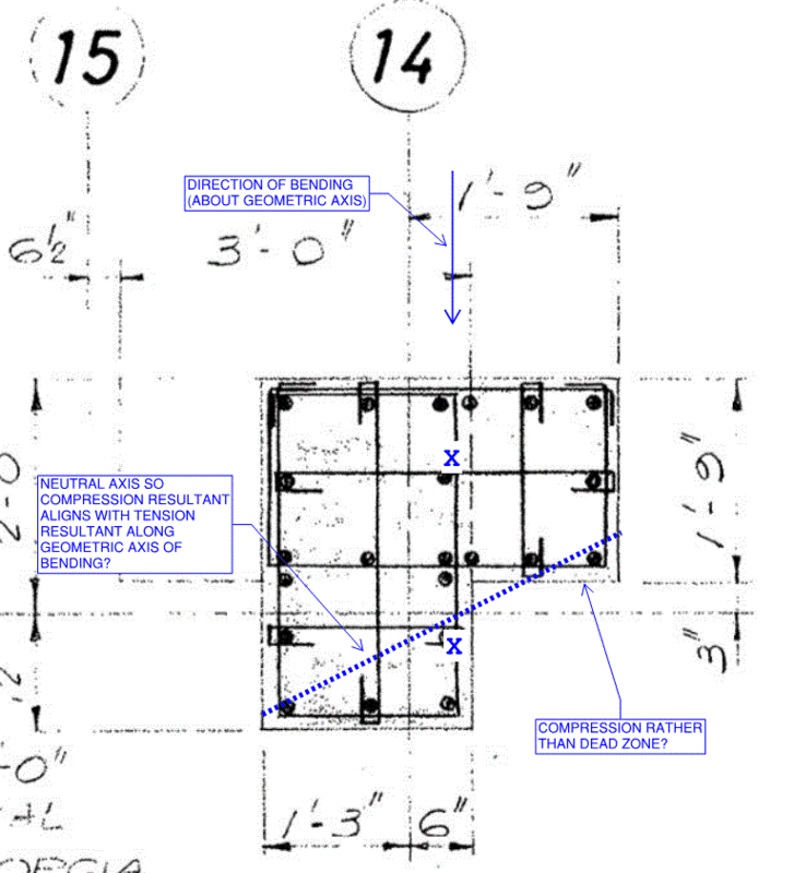
Next, I’d like to look at the case posted by KootK in relation to the idea that the column can be treated as two rectangles for the two geometric directions. For the compression block with the neutral axis parallel to the geometric axis, this would actually be biaxial bending because of the offset between the compression resultant and the tension resultant as shown in the image below. Whilst I’m not saying the two-rectangles idea would necessarily say the section passes when it actually fails, the capacity for the smaller shear force direction may be overestimated if the concrete contribution is taken in full, as there is no compression block in that rectangle. Maybe there’s a bending plane where this does become critical (closer to 45 degrees).

biaxial_kgz3nh.gif


Last, I’ll put forward bending confined to a geometric axis, for comparison to uniaxial bending/shear that only engages one of the rectangles. I believe that the neutral axis would be tilted so that the compression and tension resultants are aligned, causing some compression in the outstand as shown and an increase in capacity of some amount compared to just the larger rectangle.

uniaxial_dlutvx.gif
 
Status
Not open for further replies.

Part and Inventory Search

Sponsor

Back
Top