Continue to Site

Eng-Tips is the largest engineering community on the Internet

Intelligent Work Forums for Engineering Professionals

  • Congratulations KootK on being selected by the Eng-Tips community for having the most helpful posts in the forums last week. Way to Go!

Timber to Timber cantilever connection 3

Status
Not open for further replies.

Aleeeex

Civil/Environmental
Aug 14, 2020
42
Hi,

This is really uncommon to me however I have tried my upmost and was wondering if you would share your thoughts.

I have 2 different sized timber beams cantilevered both which are supported by steel column. The top timber beam overhangs the bottom with a distance of 2.1m from the steel column. I have come up with the following connection. I used 20 M12 and the utilization is 0.89.

I have checked the following

1- bolts capacity perp to the grain
2- timber beams tensile stress along the grain, and shear stresses.
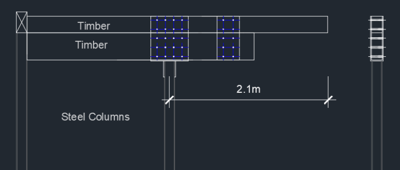
image_rvvqlu.png


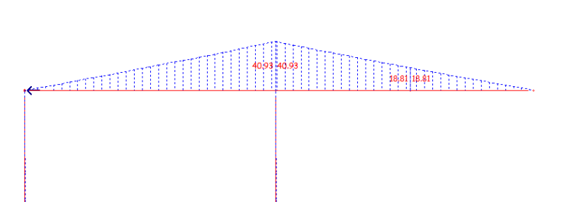
Bending Moment

image_zc5sxa.png


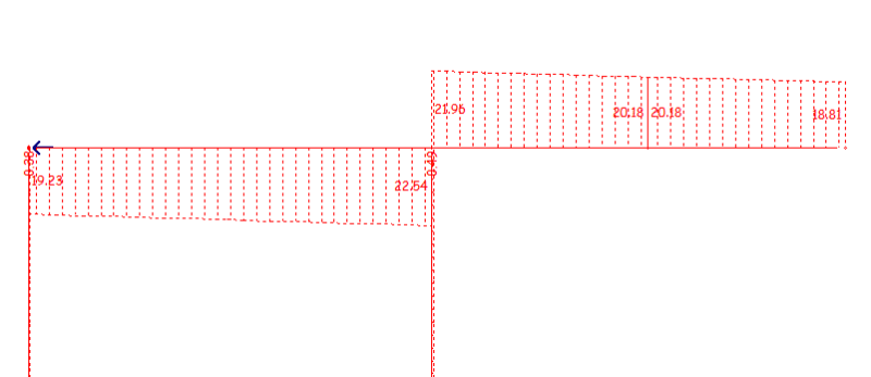
Shear

image_t91c9x.png


Thank you for your input.
 
Replies continue below

Recommended for you

What's the question here?

I'm not seeing why the bolt capacity parallel to the grain is that relevant here? The loads are transferred vertically between the members and the post, and vertically between the two members aren't they?
 
Maybe too many bolts... they may cause splitting if the lumber shrinks.

Rather than think climate change and the corona virus as science, think of it as the wrath of God. Feel any better?

-Dik
 
What’s the question? Are you aiming for composite action?
 
Like I mentioned, this type of design is unfamiliar to me.

What methodology would you use to fix both of the timber beams together?

What forces would you consider?

cheers guys!
 
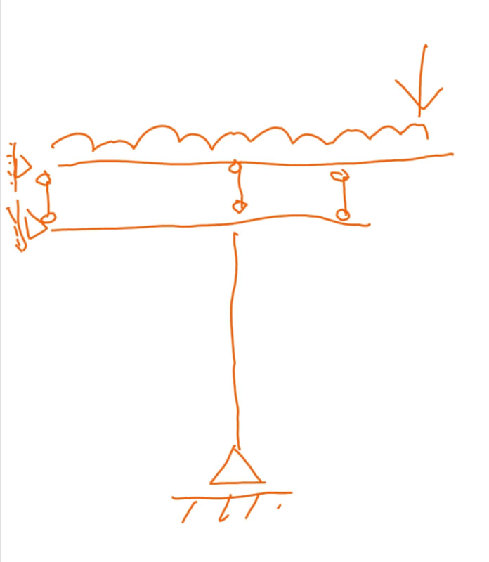
I usually check this type of thing with two separate members separated vertically by a nominal distance, but linked vis some rigid links at the points where you've connected them. This allows you to design each member for the loads being transfered between the two members. The load in the vertical rigid links can be used directly to design the transfer forces at the connection points.

The key is you basically have two separate members simply sitting on top of one another, not a 580mm deep composite member.

If you're trying to make a single member that's 580mm equivalent depth, I don't believe you can really do it connecting via bolts as shown. Composite action is undone by bolt holes being oversized typically.

 
AGENT 666:

Thank you for your help,

"I usually check this type of thing with two separate members separated vertically by a nominal distance, but linked vis some rigid links at the points where you've connected them. This allows you to design each member for the loads being transferred between the two members. The load in the vertical rigid links can be used directly to design the transfer forces at the connection points."

Please could you elaborate using a sketch example. I'm not sure I fully understand.


Bad sketch on phone follows. Hopefully it gives you a better idea of what I meant.

20201214_054535_jr5l6t.jpg
 
If you are trying for composite action, it's best to use adhesive. You may have difficulty finding technical data. You can use steel shear plates and glulam rivets. If strength is provided by the individual members you can use a couple of straps bolted to each member... use single bolts, one on each side of the joint.

Rather than think climate change and the corona virus as science, think of it as the wrath of God. Feel any better?

-Dik
 
Thank you AGENT 666: You are a star.

I followed your approach and I am quite happy with the member sizes.

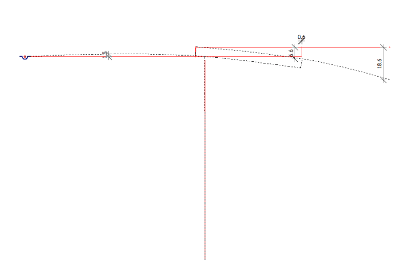
This is a model

image_ae8rxz.png


I think to use similar connection to strong Tie column cap. However, in one case I got high axial force on the column and I don't think the bolts would be enough. So I was thinking to just use the top column cap welded to the column without the bolts below .

This is how I plan to fix it.

image_elfjko.png


Please give me your thoughts
 
If you glue the two beams together for composite action you will get less deflection but you will also have lower load capacity at the end of the cantilever due to the stress concentration where the beam stiffness suddenly increases.
 
I'd move the left plate over a couple of inches and move the the bolts closer together... a couple of inches from the interface.

Rather than think climate change and the corona virus as science, think of it as the wrath of God. Feel any better?

-Dik
 
Compositepro said:
If you glue the two beams together for composite action you will get less deflection but you will also have lower load capacity at the end of the cantilever due to the stress concentration where the beam stiffness suddenly increases.

You've got to be kidding!!

BA
 
AndyWat:

To design these beams as a composite section, you need to calculate the horizontal shear between the two beams and provide enough glue or other fastening to resist that shear.

To design them as two individual beams, it is necessary to determine compatible deflections. That is not a trivial exercise.

Show the loading diagram, particularly the one where the axial load to the column exceeds 165kN.

Why are you selecting this odd arrangement of beams?

BA
 
I’d run the top beam further into the backspan. More like that agwnt666 showed.
 
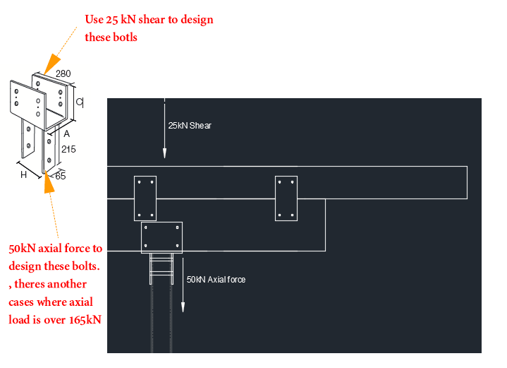
The client doesn't want the beam below sticking out. So I have to add beam inline with the roof joists and can give extra support. That cantilever is carrying only 25kN point load and the self weight.


image_uh8as0.png


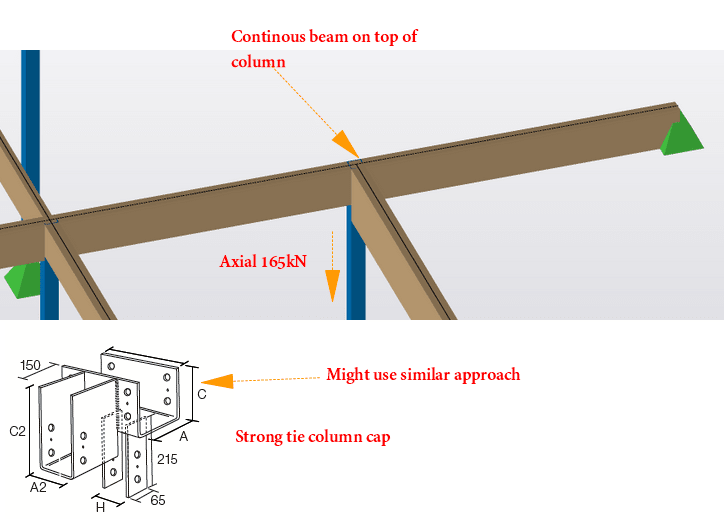
The other case where I got 165kN is at a T junction

image_gxbhgo.png


I may use T junction but I dont think 2 bolts would be enough at the bottom. Please advise
 
Depending on the beam dimensions, long self-tapping screws might work, driven down through the top surface of the top beam. That'll provide both shear flow resistance for composite action, and clamping for some belts-and-suspenders adhesive. Your local contractors may have a favourite vendor, around my parts GRK is in vogue.
 
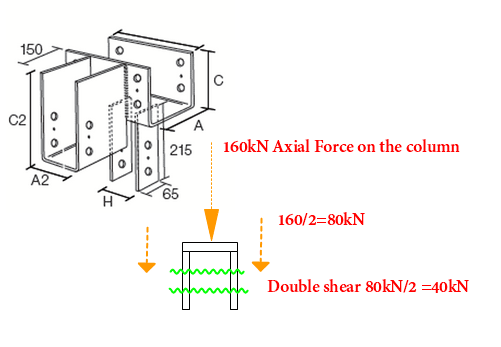
I am also concerned about the T junction connection as I got high axial force 160kN in there. I did some check as you see below, but I am not sure if the connection is designed using this approach. I used M16 grade 8.8 and plate thickness 12mm.

image_m6e5d4.png


Using bolt size 16mm

Bolt double shear capacity 118kN > 40 KN

Bolt bearing capacity for 12mm plate thk = 88.3 kN > 40 KN


Please give me your opinion in case I missed something
 
For the downward forces, they are relying on bearing of wood on steel. The bolts are only there to hold everything in place and transfer any uplift loads.
 
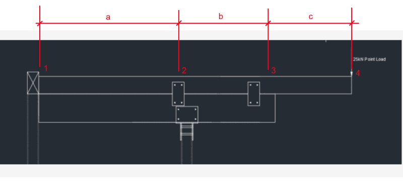
See diagram below. Point 1 is the face of column (or more correctly, the centre of hanger). Point 2 is the centre of a plate connecting the two beams. Point 3 is the centre of bearing area between the two beams. Point 4 is the centre of load application. Dimensions a, b and c are as shown below.

The plate just left of point 3 holds the top beam in place but does nothing structurally.

Red text below has been edited.
In the absence of plate 2, the top beam would be supported at points 1 and 3. Neglecting beam weight, the reaction at point 3 in kN would be 25*(a+b+c)/(a+b). The reaction at point 1 would be 25*c/(a+b) upward. Between points 1 and 3, the top beam would arch upward relative to a straight line between points 1 and 3. Point 3 would deflect downward and the lower beam would deflect upward between points 1 and 2. The amount of arching of each beam depends on their stiffnesses. If the lower beam is the same width and 1.5 times the depth of the upper beam, its stiffness is more than three times as stiff, so the upper beam would never come in contact with the lower beam except at points 1 and 3.

If a plate is included at point 2, tying the two beams together, that plate would be in tension, the value of which is indeterminate. This means that the other reactions are also indeterminate.

Nothing I have said above should be a mystery to anyone with an elementary understanding of statics.


image_zqcury.png


BA
 
Status
Not open for further replies.

Part and Inventory Search

Sponsor