Continue to Site

Eng-Tips is the largest engineering community on the Internet

Intelligent Work Forums for Engineering Professionals

  • Congratulations KootK on being selected by the Eng-Tips community for having the most helpful posts in the forums last week. Way to Go!

OK to Ignore Portion of Diaphragm?

Status
Not open for further replies.

codySTR

Structural
Dec 28, 2017
32
I am determining the lateral force distribution through a wood-framed apartment building. Hardly any of the shear walls align across the central corridor. Also, there is a geometric irregularity that I haven't seen discussed anywhere: the corridor curves.

So, my main question is really: Is it "OK" to ignore the portion of the corridor that curves for the purpose of determining the forces in the diaphragms, collectors that "matter", and the shear walls? I just don't know how to account for the curve and resulting layout of diaphragms and collectors.

When I say "matter", what I am suggesting is that the way I have subdivided my diaphragms results in a chunk or group of "sub-diaphragms" that are bounded on 3 sides by collectors and only have a shear wall on one side. Can I effectively remove this whole chunk to determine all of the resulting forces in the remaining diaphragms/collectors/walls? Does that make sense?

Wetransfer link to PDF showing floor plan, diaphragms, and basic diaphragm shears: [URL unfurl="true"]https://we.tl/t-4lSD4xm6uW[/url]
 
Replies continue below

Recommended for you

For wind, I'd approximate the curve with a large rectangle that covers most of the area - probably okay to clip the corners off a bit and ignore some of the gradual curves. That will give you a more conservative estimate of tributary loads going to the adjacent shear walls and collectors. Then, use the cantilevered diaphragm rules for that rectangle, which will have a comparable cantilever to the actual curved diaphragm.

For seismic, you could probably get away with something similar, but I haven't done any multistory wood analysis that required more than a cursory look at seismic loads to verify they're less than wind. I'd defer to folks in earthquake country for that.
 
Sure it's okay to ignore the curved portion. If you can satisfy equilibrium without including certain resistances which are difficult to include, you should be on the safe side. Any contribution from the portion you have ignored is gravy.

BA
 
Pham and BA: Both of your suggestions seem reasonable to me. I suppose I'm leaning towards what you're thinking, BA. That is ignore the complex stuff, satisfy equilibrium with the lesser number of diaphragms/collectors, and get conservative shears in the elements I am accounting for. And like you say: "Any contribution from the portion you have ignored is gravy."

For clarity: I'm in a wind-dominated area. Seismic isn't a real concern.
 
Absolutely! This is practical engineering. Use your best judgment about what is a reasonable way to APPROXIMATE the behavior of the structure well enough to come up with a good and safe design. We're not writing a PhD thesis, so just do the best you can do.

 
1) In general, I agree that this probably isn't a huge deal.

2) Frankly, your analysis is much more detailed than I typically see. So you are the thesis guy, not the shortcut guy.

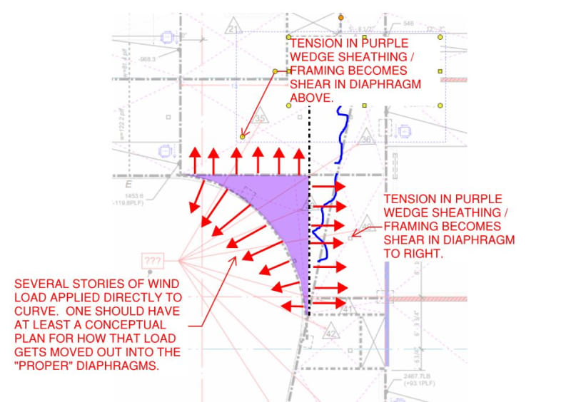
3) I feel that wind is actually more critical to this situation than seismic because wind will be applied directly to that curved wall face no matter where it ultimately gets resisted. See the sketch below. I feel that, at minimum, you should develop a conceptual plan for how wind applied to that curved face makes it's way over to your "real" diaphragms and shear walls.

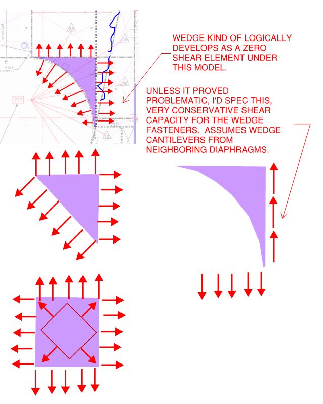
4) We normally consider our diaphragms as conceptual shear panels, carrying no axial stresses between boundary members. As shown below, I feel that the purple wedge will represent a departure in this respect. I feel it reasonable to assume that the purple wedge will transmit its load to the adjacent diaphragms via in plane tension in the deck and/or framing. As such, I think that it's important to recognize this mechanism and allow it to influence you detailing choices where prudent.

C01_mdrepq.jpg
 
I'd certainly specify some diaphragm shear capacity for the wedge, maybe something like this. I would hope that it would amount to little more than just continuing the fastening pattern from the adjacent diaphragm panels through.

C01_o8ahyq.jpg
 
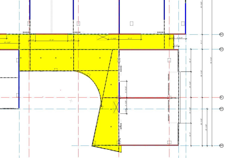
Thank you all for your input thus far! I do tend to get bogged down by trying to figure things out the "PhD" way. Bad habit. I should point out that there is not an exterior wall actually along the curved corridor. In the image below, the yellow highlighted portion is all open-air corridor. There will be steel columns and either steel or timber beams along the "free edge" of the curved portion.

corridor_highlight_xrzndw.jpg
 
More or less the same answer from me then. The yellow stuff will either need its own, independent lateral system or it will need to be made to ride along with the macro structure.

Are the yellow bits essentially canopy structure between sections of multi-story, enclosed building?

Any chance you could post an elevation of this area?
 
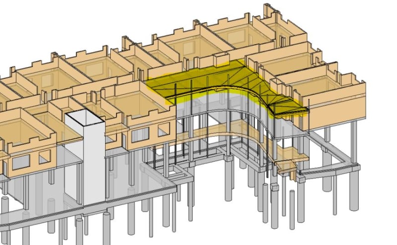
Koot, here is a 3D view focused on the curved portion. The elevation view is pretty wacky to look at. The highlighted area is the first level of wood framing above a PT concrete podium. There are 3 additional levels above this (2 floors + roof) all with matching layouts.

Curve_3D_View_y4q7j6.jpg
 
Thanks for the isometric. The situation is much clearer to me now. One thing to consider is that the columns supporting the curved area will derive their lateral stability from the diaphragm bits that they are attached to. It doesn't take much to get that job done but you do want a somewhat robust load path for the bracing function.
 
KootK said:
Thanks for the isometric. The situation is much clearer to me now. One thing to consider is that the columns supporting the curved area will derive their lateral stability from the diaphragm bits that they are attached to. It doesn't take much to get that job done but you do want a somewhat robust load path for the bracing function.

Attention to detail. Focus on the load path. We always can rely on KootK to give us some good perspective.

It's interesting, I don't recall much discussion on "load path" when I was in college. Nor was there much discussion of connections or detailing. Likely because my University (at the time) did NOT offer any classes in wood design.

Regardless of why, I'd wager that if you asked practicing engineers in a survey, those two things would probably be the top items that they think will insure the intended behavior of their structures.

Maybe also something like "using construction drawings to clearly communicate with the contractors / fabricators / suppliers".
 
Good point there, KookK.

Agreed about the lack of instruction in school on load path and connections (of any material, in my opinion). I missed my chance to take a wood design course as an undergrad when it was actually offered. Sadly, wood wasn't even offered by the time I was in grad school. Most engineers I know say "oh wood and masonry are easy to pick up" but personally I benefit from formal education.
 
Masonry, in my experience, is pretty easy. The material behavior is similar to concrete. But, the design codes are simplified.

But, wood?! I personally think wood structures are the most difficult to deal with. Nothing is ever clean with wood buildings. Roofs aren't flat, detailing is a pain, load paths can be difficult, electricians and plumbers are always cutting up your structural members. There always seems to be goofy geometry you have to work with.... contractors are often cheap, inexperienced and incompetent.
 
Status
Not open for further replies.

Part and Inventory Search

Sponsor