Continue to Site

Eng-Tips is the largest engineering community on the Internet

Intelligent Work Forums for Engineering Professionals

  • Congratulations KootK on being selected by the Eng-Tips community for having the most helpful posts in the forums last week. Way to Go!

Retaining Wall Negative Bearing Pressure? Negative Moment?

Status
Not open for further replies.

Redacted

Structural
Mar 12, 2016
160
Hi There,

I am currently designing a retaining wall. The architect would like a 6’8” retaining wall, although the height of the embankment is 14’, which will require a sloped backfill.

As a result the foundation ended up being quite large, when considering the height of the wall. I am calculating the bearing pressure but am running into some calculations that are raising some questions and I would like to know whether I am going about this the right way?

I attached the calcs to this thread but I am getting a negative moment when taking moments about the centerline of the base.

I am getting a negative pressure at the toe and positive at the heel. The negative toe pressure would cause the heel pressure to increase higher than what I show in the calcs. What is the formula to calculate the accurate heel pressure?

Although the toe pressure is negative, I can only see that being realized in the heel pressure exceeds the allowable bearing capacity of the ground, which is unlikely.

The stability checks for the wall were fine for sliding and overturning.

Any help would be appreciated, as I am not sure if I went about these bearing pressure check cals the right way.
 
 https://files.engineering.com/getfile.aspx?folder=c81c92f3-b398-476c-8b3e-cfd6b3a90a9f&file=EngTips_Review.pdf
Replies continue below

Recommended for you

CRSI has good references for simple retaining walls. And there are many others as well, including PE exam prep books.
It looks like you could use some example calcs. I honestly could not figure out what you were doing in your calcs - they do not follow conventional practice.

For point of rotation and summation of driving and resisting moments, I suggest the ftg toe (not the footing centerline).
 
Review topics around the Kern point/zone for the foundation.

Soil only really provides compression resistance, so if by using the standard P/A +/- M/S you find one side is negative what that really means is that side experiences tension which can't happen for a material that provides compression resistance only. This tells you that your resultant force is outside of the Kern zone which means that you need to find a bearing pressure distribution which has a resultant reactionary force in line with the applied resultant force to maintain equilibrium. This usually means a triangular pressure distribution. In my experience the concentrated triangular distribution when outside the kern is not validated by the typically geotechnical recommendations so if you are unable to get a geometry such that you get back into the kern zone, where at the worst case P/A +/- M/S yields 0 on one side, you should touch base with the geotechnical engineer to verify the concentrated triangular distribution is acceptable.

My Personal Open Source Structural Applications:

Open Source Structural GitHub Group:
 
Hi all,

Thanks so much for the responses so far.

@ATSE, Yes example calcs for a similar situation to this would be helpful. As the wall has a sloped backfill (to my knowledge) you can't use the standard ka=(1-sin(angle))/(1+sin(angle)) and you need to use the rankine formula I included in the calcs to adjust the ka value to reflect the inclined slope.

See the following document :
The increased ka value is causing issues with sliding, which is what has created the need for such a large foundation given the size of the wall.

@Celt83 Yes, that is exactly the problem. My moment itself is negative and as a result of this moment being negative the standard P/A +- M/S is giving the negative value on one side. What I was looking for was a way to calculate what the true increased value on the heel side would be as a result of the negative pressure. Logically (although I could be wrong in my thinking), wouldn't the negative pressure only become an issue if the ground fails in bearing at the heel? If not the front could never be in tension. This is why I would like to calculate the increase to see if the heel is within the allowable bearing pressure.

I would struggle to get the geometry to work by getting a positive pressure because it would require me to reduce the width of the heel, which was required to pass the sliding check. Any ideas on geometry optimization would be greatly appreciated as well!

Unfortunately, there is no geotechnical engineer available to assist with this.
 
Rstars said:
..because it would require me to reduce the width of the heel, ..
I would revisit this as the statement doesn't make sense. Reducing the heel will reduce S which in turn will increase the M/S term which would yield more "tension", I put tension in quotes because again tension is not possible in this system.

Rstars said:
..My moment itself is negative and as a result of this moment being negative the standard P/A +- M/S is giving the negative value on one side. ...
Review your sign convention and make sure you make it clear to yourself what positive and negative results mean, as a check on your sign convention resolve your forces to be a single load P applied at some eccentricity e this way you can visually identify where the vertical soil resultant reaction wants to end up. As ATSE recommended try summing moments about the bottom exterior corner of the Toe.

Rstars said:
Logically (although I could be wrong in my thinking), wouldn't the negative pressure only become an issue if the ground fails in bearing at the heel?..
So again tension is a physical impossibility of the system so if your static equilibrium requires tension then your calculations are incorrect and it's not just a matter of simple adding the tension to the compression side.

Here is one approach:
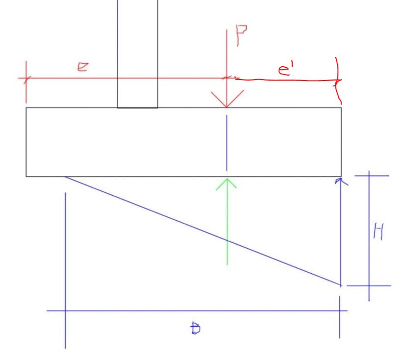
As above resolve all of your forces to a P at some e from either the toe of ftg centerline. For static equilibrium we know the sum of vertical forces must = 0 and sum of moment must = 0.

Assumptions:
1. no tension is possible at the soil ftg interface (compression only reaction)
2. There is a force unbalance, P*e, so the pressure distribution will be assumed to be triangular. (your initial calc where P/A +/- M/s yields opposites signed results confirms this)
3. calculations are based a unit width of footing

using the above we know the total soil reaction must be P. To turn this into a triangular distributed force (pressure) realize that for sum of moments to = 0 the soil reaction must be applied at the same location as the resultant P. Area of triangle is 1/2 B*H and centroid is either located a 1/3 B or 2/3 B depending on which side your measuring from.
You can solve for B directly using the sum of moments equilibrium equation and then substitute to solve for H, where H is the peak bearing pressure and B is the width of bearing.

stepping into it, lets define an second eccentricity called e' which will be the distance from the location of peak bearing to the resultant force P.
sum Fv = 0:
P = P,soil

sum Moments = 0:
P*e' = 1/3 *B*P --> B = 3*e'

Back substitution of B into area of triangle formula to find H:
1/2 *B*H = P --> 3/2 * e' * H = P --> H = (2 * P) / (3 * e')

EDIT: the image doesn't necessarily represent a retaining wall, for a retaining wall the peak bearing pressure will usually be beneath the toe (more or less mirror image of below)
Capture_orrgfz.jpg


My Personal Open Source Structural Applications:

Open Source Structural GitHub Group:
 
Re-check this calculation:

Screenshot_20210126-075533_Drive_ttowby.jpg


The increased ka value is causing issues with sliding, which is what has created the need for such a large foundation given the size of the wall.

You want more footing under the retained fill to control sliding, rather than extending the footing to the side with no fill over it.
 
Thanks @Celt83

What you have written is very helpful. In all honesty I am a bit confused, apologies as it is my first time doing this and I am not experienced in this.

As you recommended I took moments about A (see attached sheet) and from there worked out the resultant as 1.914m from A (is my method for calculating this correct)?

I am now trying to calculate B but am stuck, would you be able to assist further?
 
 https://files.engineering.com/getfile.aspx?folder=6b57b64b-ce15-42c1-920c-07219f892ddf&file=Eng_Tips_Review_2.pdf
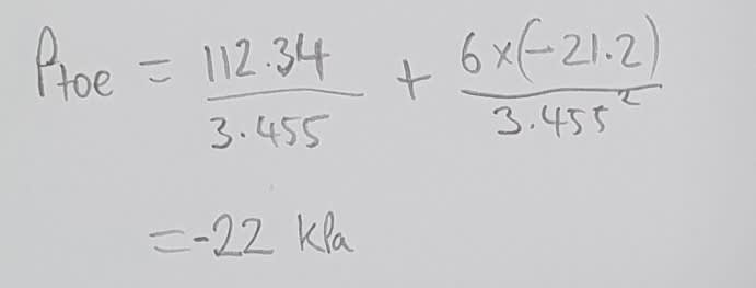
@Steveh49 Thank you! That seems to be what was causing the issue, although I am still a bit confused as to why the moment is negative. I'm assuming this is because the main pressure is in the heel. I just want to make sure that the N/D+6M/D^2 equation is valid with a negative moment?

Regarding the size of the footing, I would have preferred to put more of a heel on. The length of the toe is something that I could not control as this is supposed to be the laydown area for a generator. If the heel is made much larger it would also start to encroach on an adjacent boundary.

 
Rstars said:
.., although I am still a bit confused as to why the moment is negative.
Reviewing your second calculation you have defined positive moment as counter-clockwise about point A. A counter-clockwise rotation about point A will tend to lift up the far corner of the heel. Your overall resultant moment is negative which means that with all the loads applied your system is trying to push the heel into the dirt, this is a good thing and shows stability.

normally you would check stability as a ratio of the overturning vs restoring moments which provides the factor of safety against overturning. Your sign convention has the overturning moment positive and restoring moments as negative, a net negative moment indicates a factor of safety against overturning of at least 1.0. It is likely your local code defines a minimum required factor of safety for overturning so make sure you check that as well.

Rstars said:
I am now trying to calculate B but am stuck, would you be able to assist further?
In your sketch, 1/3 B should align with R.

Edit:
Per SteveH49's post there was an error in your original P/A + M/S calc, which means you actually have a trapezoidal bearing profile so the triangular method I noted will not be applicable. This goes back to reviewing the Kern point/zone.


My Personal Open Source Structural Applications:

Open Source Structural GitHub Group:
 
In your second set of calcs, you're showing a triangular bearing pressure distribution with maximum at the toe. But your calcs show that you have compression over the entire base (trapezoidal distribution) because the resultant is within the middle third of the base. The negative moment indicates that the maximum is at the heel, not the toe.

Don't get too hung up on rules of thumb for base width. They're based on having a toe width of zero to ~1/3 of the overall base width, which is usually efficient for this type of wall. You have been told to extend the toe for the generator. This is good for overturning and bearing but almost irrelevant for sliding, so your base will be wider than typical. Or go deeper to get passive soil resistance.
 
Status
Not open for further replies.

Part and Inventory Search

Sponsor