Continue to Site

Eng-Tips is the largest engineering community on the Internet

Intelligent Work Forums for Engineering Professionals

  • Congratulations waross on being selected by the Eng-Tips community for having the most helpful posts in the forums last week. Way to Go!

Metal roof without plan bracings 1

Status
Not open for further replies.

struggle67

Structural
Mar 29, 2013
116
SG
Hi
Do you guys do metal roof without plan bracings so called belt truss? Below picture is the model used for a software training I attended. Purlins are LTB restraint to truss. There was no problem with software analysis and design. But I am curious where do all the LTB restraint loads from purlins go without plan bracing? Is there any load path that I am not aware?
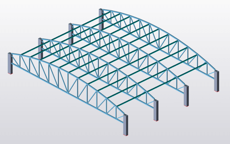
Capture_niiiis.png
 
Replies continue below

Recommended for you

Normally, the roof diaphragm (properly braced) would resist the bracing forces. If you don't have a roof diaphragm, you should use diagonal bracing in the plane of the roof to get the bracing forces to the lateral force resisting system.

DaveAtkins
 
I would imagine that the connections between the purlins and the trusses (in the vertical plane) were modelled as moment connections in your software.
 
1) In north america, it is common to use the roof sheathing itself as a structural diaphragm to brace the roof framing and building as a whole.

2) In some, other parts of the world, roof sheathing is not used as a structural diaphragm. So it's a function of your region's accepted practices in part.

3) where roof sheathing is used as a structural diaphragm, one must ensure that the sheathing has the capacity to perform that function. Standing seam metal roofing, for example, typically does not.

4) the particular building form that you've posted is one for which I would normally expect to see discrete, in-plane braving of the type that you're imagining.


Hi struggle,

- Purlins are LTB restraint to truss O.K.
- Roof claddings are LTB restraint to purlins OK if some conditions satisfied,

But still u may need plan bracing to transfer wind loading to vertical bracings..
Consider the wind loading for front wall ( together with gable wall ). What is the load path ?

Let me more specific;
End wall cladding transfer wind loading to end wall girts and girts to vertical posts and posts transfer half of the horizontal load to end wall rafter ( in this case truss) so to the purlins..
The question is, can the roof sheeting ( with corrugated direction paralel to end wall ) transfer the wind loading to VB ? If yes you do not need HB.

If the steel truss is supported on steel columns and if the end wall posts laterally supported by roof truss, IMO, you will need HB.


struggle67 said:
There was no problem with software analysis and design.
Says who? The software? The trainer?

Sure the software might have "no problems" but if the inputs aren't reflective of reality then you end up with a model of rubbish in and rubbish out. Plan bracing in roofs isn't generally to stope LTB, it is often there to transfer lateral loads to the wall and if your walls are just cladding then you'll probably want some wall bracing to to transfer the lateral loads from the roof to the floor.

Additionally the truss does not seem to have appropriate LTB restraint for uplift. Whether this is a problem or not depends on the relative loads dead weight vs wind uplift.
 
Thank you guys,

After I check the trainer's model again, I found that the purlins are not functioning as LTB restraints (i.e whole purlin just moved/slid) and the truss buckling/deformed shape is from start to end of truss, not purlin to purlin as the trainer claimed.

I guess for training they just focused on modeling aspects. too bad for me and sry to have disturbed you all. Anyway thanks for clearing my doubt.
 

Not sure how did you decide that ( the purlins are not functioning as LTB restraints (i.e whole purlin just moved/slid) and the truss buckling/deformed shape is from start to end of truss).. Will you pls explain?

Apparently the truss column connection is rigid and that is, compression force will develop at bottom chord portion around column. So you may need struts for bottom chord also..

human909 (Structural) has a valid point..(Additionally the truss does not seem to have appropriate LTB restraint for uplift.)..
and a pink star for that..
 
Hi HTURKAK,

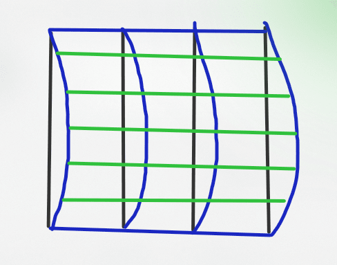
Sorry for the late reply. Now I don't have access to the model but I sketched this below to explain why I concluded Lcr is full span length.

Capture_jzrbhm.png


This is the plan view.
Black color - original truss position
Blue Color - Deformed/Buckled shape. Lateral deflections of trusses are around 150-200mm but if I need plan bracing, it will reduce to a very minimum deflection <20mm.
Green Color - purlins.

Apparently the truss column connection is rigid and that is, compression force will develop at bottom chord portion around column. So you may need struts for bottom chord also..
Noted Thanks.
 
Status
Not open for further replies.

Part and Inventory Search

Sponsor

Top