1) There is currently another, interesting, active thread here on shear flow that you might enjoy checking out:
Link. It's the reason that you're seeing so much attention paid here to connector forces transverse to the member, particularly at the ends.
2) I believe that the shear flow equation that you've been attempting to apply is indeed applicable to the case of your thought experiment. That said, it's obviously not jiving with your intuition so, in a an effort to help with that, I'll attempt an intuitive response to the best of my ability:
INTUITIVE EXPLANATION
We structural engineers are basically students of Newtonian physics. As you'll recall with Newtonian physics, many sorts of things are
conserved. Energy, mass, whatever...
There's no such thing as a free lunch is one, somewhat pessimistic, interpretation of that conservation. Everything has a cost. But the reverse is also true in that, when you're only asking for, say, a fig newton and a box of apple juice, lunch is actually pretty cheap. The cost is commensurate with the benefit. Nature never asks that you
over pay.
When we attempt to make two independent sections behave compositely:
1) The cost is how onerous the fastening requirement is and;
2) The benefit is the degree to which the composite moment of inertia is increased relative to the sum of the original, non-composite moments of inertia.
Looking at some extreme cases:
A) Where the two constituent members have their centroids on the same vertical axis, composite behavior yields no improvement at all with respect to the moment of inertia. The lunch tray is empty. Commensurately, the cost is zero with respect to horizontal shear connection demand.
B) Where one constituent member is stacked above the other, the composite moment of inertia is the maximum that it can be without introducing a physical separation between the two members. The lunch is hearty and nourishing. Commensurately, the cost is substantial in reflection of the benefit received.
In your hypothetical arrangement, the composite moment of inertial is only marginally more than the sum of the independent moments of inertial. Thus. you are closer to having an empty lunch tray and the horizontal shear demand is small.
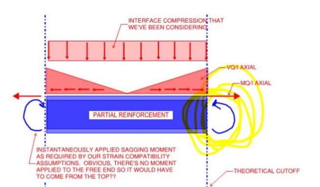
3) In that other thread that I referenced, we arrived at a fairly robust free body diagram of the the reinforcing piece considered there. The same model should apply quite well to the inner tube of your case. Note, in particular, that that composite action involves five actions imposed upon the reinforcing piece:
i) Distributed horizontal shear, VQ/I.
ii) A distributed, transverse load applied upon the reinforcing by the main member through the interface connection.
iii) A concentrated, transverse load applied upon the reinforcing by the main member at the the ends of the reinforcing and opposing [ii].
iv) Where the reinforcing does not extend the full length, a concentrated horizontal shear, MQ/I.
v) Where the reinforcing does not extend the full length, a concentrated moment at the ends of the reinforcing.
4) I've done a fair bit of curtain wall reinforcing design and these are my thoughts on how it should be done:
A) Recognize that almost nobody does this 100% correctly. Or even close.
B) If you've got the packing at the ends, you really don't have to worry about [iii] above.
C) For one wind direction, [ii] will be resolved by the main member pushing against the reinforcing and creating no axial demand in the fasteners (only the shear). For the other wind direction [ii] needs to be resolved by the member pulling away from the reinforcing and creating a tension demand in the fasteners which should be combined with the VQ/I shear demand.
D) Per AaronMcD, it's pretty common to assume that the two members are
not composite owing to uncertainties regarding connection slip etc. At least that's the case when the benefit to the moment of inertia is quite modest as I discussed in [#2]. So design the fasteners for composite behavior but consider ignoring the composite action for the macroscopic design of the composite member.