jaskamakkara
Structural
I am detailing a portal frame that has HEB260 columns and IPE600 rafters. I am trying to detail the proper restraint to the columns at the level of the base of the haunch. I am using SCI documents P397, P399, and P252 (which all pertain to portal frame design) as references but I have some questions.
I don't really have the possibility to restain the columns using side rail stays to the inner flanges, owing to the nature of the side rails and cladding system, so I need use steel members (eaves struts) along the length of the building at haunch level which are tied into the vertical bracing. I am little confused by the recommendations given by the SCI regarding this:
Here is what they show in a diagram taken from P252:

Figure 1
So they are saying that a tube section near the compression flange of the column can act as both an eaves tie (for stability and robustness) and as a restraint for the column. Great. But now here is some supporting text (this is present in all 3 documents in some form):

Figure 2
So I get that if you use this eaves strut to restrain the columns then it needs to be tied into the vertical bracing to transfer those loads down into the foundation. Great, get that, but here is some more text from P399:

Figure 3
And this text from P252:

Figure 4
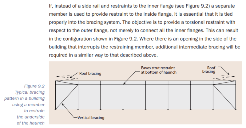
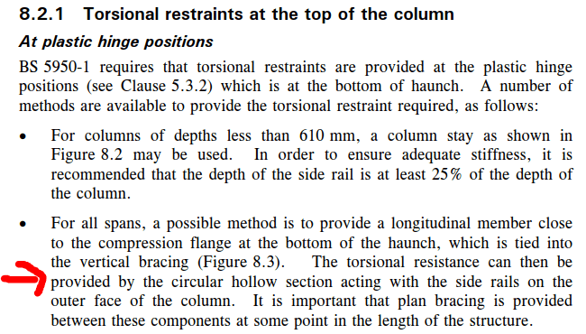
So it seems to me that Figures 3 and 4 are slightly in conflict (Figure 4 is from the older document). Figure 3 suggests that I can have an inner flange eaves strut along the length of the building which is then tied into the vertical bracing (as in Figure 2) and I'm all sorted. Figure 4 seems to suggest that the eaves strut should be tied into the vertical bracing AND somehow tied in plan into the side rails/cladding/whatever on the outer flange. Figure 4 makes more sense when are talking about making a torsional restraint, but maybe is Figure 3 suggesting that the torsional restraint is provided by simultaneous lateral restraints on the inner and outer flanges - inner from the eaves strut/vertical bracing, and the outer from diaphragm action in the cladding?
What are your thoughts on this? If I provide an eaves strut with vertical bracing near the inner flange of my columns, and leave the outer flange with the cladding only (which will be timber joists supporting some kind of thin cladding material) is that sufficient? Or do I still need the plan bracing between the inner and outer flanges of the column?
Hopefully this makes sense, I can provide more details if required.
I don't really have the possibility to restain the columns using side rail stays to the inner flanges, owing to the nature of the side rails and cladding system, so I need use steel members (eaves struts) along the length of the building at haunch level which are tied into the vertical bracing. I am little confused by the recommendations given by the SCI regarding this:
Here is what they show in a diagram taken from P252:

Figure 1
So they are saying that a tube section near the compression flange of the column can act as both an eaves tie (for stability and robustness) and as a restraint for the column. Great. But now here is some supporting text (this is present in all 3 documents in some form):

Figure 2
So I get that if you use this eaves strut to restrain the columns then it needs to be tied into the vertical bracing to transfer those loads down into the foundation. Great, get that, but here is some more text from P399:

Figure 3
And this text from P252:

Figure 4
So it seems to me that Figures 3 and 4 are slightly in conflict (Figure 4 is from the older document). Figure 3 suggests that I can have an inner flange eaves strut along the length of the building which is then tied into the vertical bracing (as in Figure 2) and I'm all sorted. Figure 4 seems to suggest that the eaves strut should be tied into the vertical bracing AND somehow tied in plan into the side rails/cladding/whatever on the outer flange. Figure 4 makes more sense when are talking about making a torsional restraint, but maybe is Figure 3 suggesting that the torsional restraint is provided by simultaneous lateral restraints on the inner and outer flanges - inner from the eaves strut/vertical bracing, and the outer from diaphragm action in the cladding?
What are your thoughts on this? If I provide an eaves strut with vertical bracing near the inner flange of my columns, and leave the outer flange with the cladding only (which will be timber joists supporting some kind of thin cladding material) is that sufficient? Or do I still need the plan bracing between the inner and outer flanges of the column?
Hopefully this makes sense, I can provide more details if required.
