Continue to Site

Eng-Tips is the largest engineering community on the Internet

Intelligent Work Forums for Engineering Professionals

  • Congratulations Danlap on being selected by the Eng-Tips community for having the most helpful posts in the forums last week. Way to Go!

Sky pool! 1

Status
Not open for further replies.

MIStructE_IRE

Structural
Sep 23, 2018
816
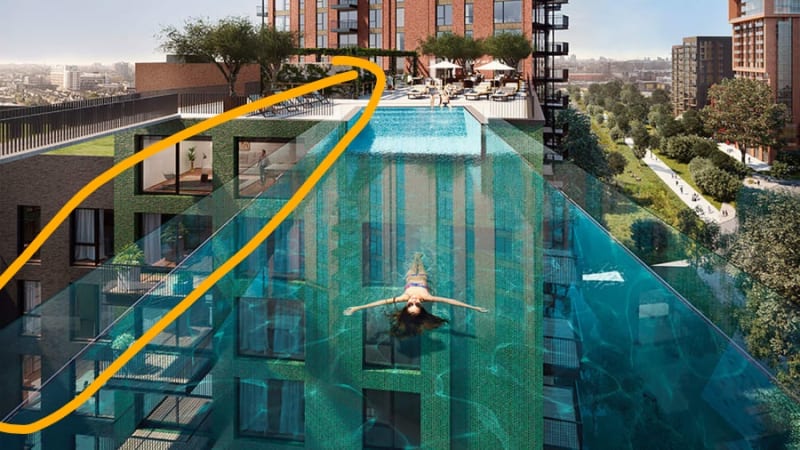
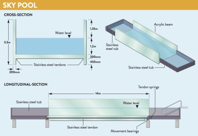
As much as this image looks like CGI, its not. Its just opened in London and appears to be made of 200mm thick acrylic. The span is about 14m and it consists of a 200mm thick acrylic slab spanning between upstand beams. These beams are 200mm thick acrylic x 3.3m high!

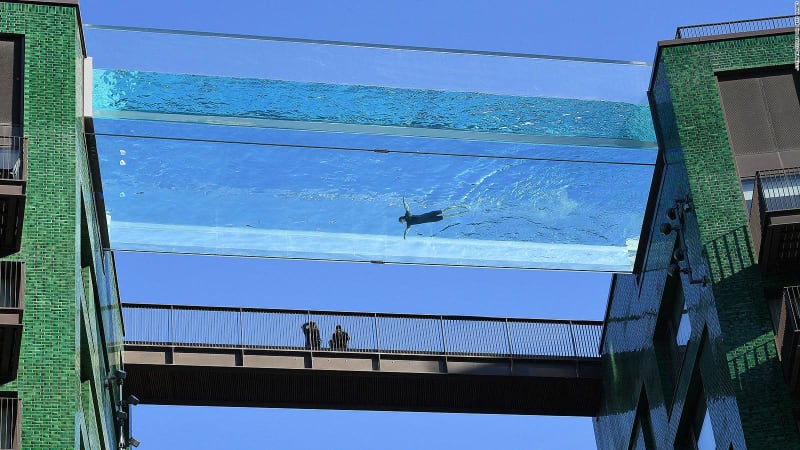
I’m still unsure as to why the compression zone of these incredibly slender upstand acrylic beams does not LTB itself into oblivion! I understand the concept of U-frame action in chunky steel bridges, but this seems to defy all understanding I have of structural behavior! Can anyone shed some light on this? Its very impressive!

Ps - for those wondering about redundancy, as I was, there are 2 No. steel cables beneath the slab..

F75E9798-47DB-4F40-9434-E9EA3A5530EE_ubn88t.jpg


D06BDBD3-2430-4FF7-B41F-F4089BA2FC1F_qrc0nq.jpg
 
Replies continue below

Recommended for you

Does the picture show a flange on the top? Which isn't shown in the cross section?
 
That is pretty cool.

1) I'm sure they looked at this, but is the Acrylic okay out in the sun long term? Or will it get cloudy/yellow?

2) I would not want to live in the apartment right below the Acrylic-to-stainless steel transition. After 5-10 years of the buildings swaying in the wind, that seems like a good leak spot.

 
this is somewhere between cool and utterly terrifying !

another day in paradise, or is paradise one day closer ?
 
It looks like there are top flanges for the upstand beams, making these upstand beams essentially angles:
F75E9798-47DB-4F40-9434-E9EA3A5530EE_ubn88t_sisfdw.jpg
 
Craig_H said:
It looks like there are top flanges for the upstand beams, making these upstand beams essentially angles:

That's probably it right there. Better than angles really... an upside down hat sections.

At the proportions involved, I suspect that this thing probably isn't even working all that hard. I'm surprised that it doesn't have guardrails on that flange though. That's a lot of faith to potentially place in drunks, teenagers, drunk teenagers.
 
Craig, I thought that too. But that line we see is the water level below the top of the ‘beam’.

I don’t think there’s any angle/top flange from what I’ve seen. Check out the youtube videos, there’s definitely no top flange.

I can only imagine the consequences of this going wrong..
 
You're right, no flange. What we're seeing in the photos is really freeboard. That explains the absence of a guard rail too.

Playing devil's advocate here:

1) A deep, solid beam will do surprisingly well with LTB. For comparison, consider how LTB is treated in CIP & precast concrete. Lot's of tall & skinny there.

2) As you pointed out, there's probably rotational and lateral restraint provided to the lower edges of the webs.

3) The tops of the webs would have a preferred direction of buckling here: inwards. I've no idea how to account for the benefit of it but the water pressure on the walls would tend to resist that. Or encourage it if buckling actually wants to go outwards due to that very pressure.

4) With FEM in the hands of a skilled operator, most anything can be evaluated.

I don't know that I'd want this on my building but I'd be willing to swim in it in a low wind.
 
I just noticed that the pool is also skewed to the buildings.

It made me think of how much the roadway and bridge people in my office argue about highly skewed bents, putting horizontal curves on bridges, and other geometry items.

I can only imagine the structural engineers receiving this job and saying...."You want me to design a pool bridge?... AND you want it skewed?"...lol.
 
So, beyond general "redundancy" what is it we're saying that those cables do? Hold up the floor slab in catenary action should the stuff above the slab fail? From a reliability perspective here, I would anticipate the joinery between the floor and walls to be the most fragile and unpredictable bit. The tensions have support springs which, to me, suggests that someone is hoping to develop some meaningful sag in the tendons under load. I can't say that I'd be too excited about sitting on that floor slab as the side walls crack off and the water spills out.
 
KootK said:
I can't say that I'd be too excited about sitting on that floor slab as the side walls crack off and the water spills out.

Yeah no kidding. Good luck not getting washed off the sides, and somehow managing to "stick" to to the wet, slippery bottom slab.

Never mind that the cascading water will hit whatever is below with catastrophic force. There's the classic video of a loader dropping a few cubic yards of water on a car and absolutely destroying it... picture that but on a bigger scale here.
 
Could the tendons be to clamp the stainless tanks and the main pool together into a single watertight assembly?

I'm not sure how those cables could hold up the actual pool.
 
Arup was involved. Thought so. And as Ussuri's link above says, the thing was prefabricated in Colorado and transported to London.
 
It says structural engineering of the pool by Eckersley O’Callahan (who are experts at fancy glass facades and the like), with Arup doing some of the “aquarium” aspects.
 
Tomfh said:
Could the tendons be to clamp the stainless tanks and the main pool together into a single watertight assembly?

I'd say so. The drawing calls out a "movement bearing" and "tension springs". I'd guess the cable is part of a tension system for an expansion joint for the acrylic.
 
Slickdeals, i get the u frame action concept and have used it plenty of times. But 3.3m high at only 200mm and retaining a massive amount of water also.. and made of acrylic?! It seems crazy to me, but they’ve obviously gotten this right and the result is impressive.
 
Status
Not open for further replies.

Part and Inventory Search

Sponsor