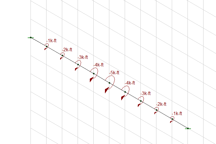
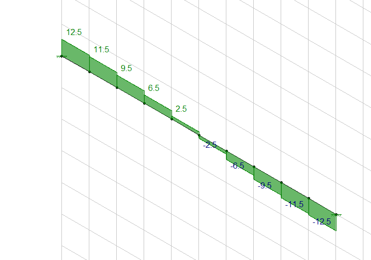
I have came across of 2 types of torsion diagram of curve beam. The torsion value is the maxiumum at the suppport and maxium at the part of teh beam which have highest curvature. May I know which one is correct ? I am confused ... I think the part which have the highest curvature (most curve) has the highest value of torsion, correct me if I am wrong...
Navigation
Install the app
How to install the app on iOS
Follow along with the video below to see how to install our site as a web app on your home screen.
Note: This feature may not be available in some browsers.
More options
Style variation
-
Congratulations cowski on being selected by the Eng-Tips community for having the most helpful posts in the forums last week. Way to Go!
You are using an out of date browser. It may not display this or other websites correctly.
You should upgrade or use an alternative browser.
You should upgrade or use an alternative browser.
Torsion diagram of curve beam 1
- Thread starter dccd
- Start date
- Status
- Not open for further replies.
To get meaningful answers here, you're probably going to have to post sketches of the situations that are producing the results that you're seeing. In my experience, most beams with torsion will have their maximum torsion at the ends. There are probably exceptions though, particularly if the beam is torsionally braced along its length.
While that may be true in some instance, I don't think that it's a principle that can be applied generally.
dccd said:I think the part which have the highest curvature (most curve) has the highest value of torsion, correct me if I am wrong...
While that may be true in some instance, I don't think that it's a principle that can be applied generally.
I think the maximum torsion would be at the ends. Similar to a straight beam with applied torsion along its length with the maximum applied torsion at the center. The below torsion moments are linear for each step along the beam and not parabolic in magnitude for each applied torsion moment. But the point moments could be manipulated based on points along a curve to get the magnitude of each applied point torsion load for an estimate, with more points if you want to get more accurate in the diagram.
Conservatively, I believe you could take the length of the straight beam to be equal to the total length along the curved beam. I would use a different straight beam diagram to estimate/superimpose the direct bending component.
The actual internal stresses are more difficult to estimate along the curved beam and would need a 3d FE model or a decent amount of hand calc time. The outside perimeter along the circular beam should have higher stresses than the interior part of the beam.


-
1
- #6
canwesteng
Structural
Depends how the beam is supported and how it is resisting the torsion. For a close section the torsion the torsional stresses are highest at the supports. For open section that isn't warping restrained at the ends, the warping torsional moment is highest at the centre.
- Status
- Not open for further replies.
Similar threads
- Replies
- 11
- Views
- 4K
- Replies
- 13
- Views
- 12K
- Locked
- Question
- Replies
- 18
- Views
- 1K
- Locked
- Question
- Replies
- 15
- Views
- 6K
- Replies
- 1
- Views
- 443
