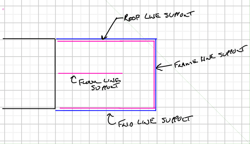
This is a carry-over thread from the Moment Frame forum where a few of us have been having some fun with a project that might progress ahead depending on what we discover here.
I’ll refer you to that thread for a detailed background but the Coles Notes are these:
[ul]
[li]We have an existing private residence that had an addition put onto the back of it (CMU enclosed) a few years ago.[/li]
[li]The owner now wants to replace the rear shear wall with a full height curtain wall.[/li]
[li]We decided on a steel portal frame to wrap the opening to provide the required lateral resistance / shear transfer.[/li]
[li]Scanned the existing CMU and found that the previous contractor short changed the owner and only poured grout w/ bar in certain areas (see pictures below).[/li]
[li]We checked to see if unreinforced + ungrouted CMU could do the job. Alas, it could not.[/li]
[li]Owner has agreed to place bar + fill cells / pretty much do any work from the outside that is required. Note: only one side is accessible from the exterior[/li]
[li]Inside is finished to the nines, it won awards, I am not allowed to touch it.[/li]
[/ul]
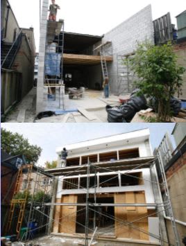
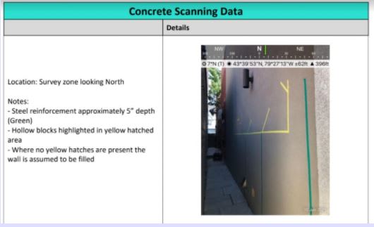
That brings us to this thread. I’ve come up with three ways of looking at the load distribution in the wall with two of them working and one failing. I am hoping you all can take a look to see if I can actually analyze the wall this way or if there is a better options or basically any thoughts.
Option A: Treat the wall as a simply supported spanning member from ground to top of roof
If you look below, you’ll see that the tensile resistance of the masonry is well overcome (1.5x) by the design force at the height where the existing grout stops. This is a problem because at that juncture I cannot drill to lap bars, and on one side of the building, I cannot do anything from the exterior. If the moment induces a tensile force in excess of the masonry tensile resistance, I think this fails with no way to reconcile the issue.
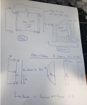
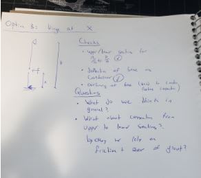
Option B: Treat the wall as hinged at the point where old grout ends and new grout begins with a fixed(ish) base
This alleviates any issue with tensile resistance as both top / bottom components work for that (top can be designed to and bottom checks out). The loads are relatively low and even when modelled as a cantilevered structure the base only deflects a trivial amount at the top (where I assume the hinge is).
Couple questions
[ol 1]
[li]Is there a reason why I cant view the wall like this? Footing connection will need to be confirmed but that'll happen when we dig for the portal frame. Presumably there is something there.[/li]
[li]What do we need to provide at the contact point between the old grout line and the new grout line? I cant add much connection via steel so I have to be comfortable with simply friction + shear resistance of the grout bed to provide the hinge. I’ve run the numbers and friction alone does the job, just barely.[/li]
[/ol]
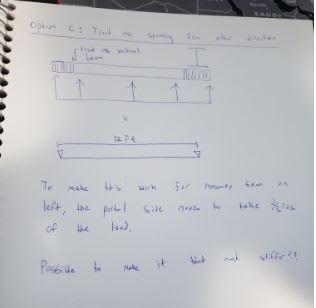
Option C: Treat the wall as spanning the 12 foot direction and consider the nearest fully grouted / reinforced masonry sections of wall vertical “beams” spanning from footing to roof
Here I would be relying on the empirical guidelines that allow for up to 16 foot spans for 10” block. The question is a matter of will the masonry act in this way?
Another complication is to make the numbers work, the masonry “beam” on the left (the one not in front of the portal frame) will need to take 1/3rd of the load. Otherwise it fails in tension. To accomplish this I’ll need to make the portal incredibly stiff + design connection from the flange to the wall for shear flow. But…I think it could be done since I can make the steel members as deep as I want.
Do people feel it would be reasonable to be able to distribute the load this way via relative stiffness?
I’ll refer you to that thread for a detailed background but the Coles Notes are these:
[ul]
[li]We have an existing private residence that had an addition put onto the back of it (CMU enclosed) a few years ago.[/li]
[li]The owner now wants to replace the rear shear wall with a full height curtain wall.[/li]
[li]We decided on a steel portal frame to wrap the opening to provide the required lateral resistance / shear transfer.[/li]
[li]Scanned the existing CMU and found that the previous contractor short changed the owner and only poured grout w/ bar in certain areas (see pictures below).[/li]
[li]We checked to see if unreinforced + ungrouted CMU could do the job. Alas, it could not.[/li]
[li]Owner has agreed to place bar + fill cells / pretty much do any work from the outside that is required. Note: only one side is accessible from the exterior[/li]
[li]Inside is finished to the nines, it won awards, I am not allowed to touch it.[/li]
[/ul]


That brings us to this thread. I’ve come up with three ways of looking at the load distribution in the wall with two of them working and one failing. I am hoping you all can take a look to see if I can actually analyze the wall this way or if there is a better options or basically any thoughts.
Option A: Treat the wall as a simply supported spanning member from ground to top of roof
If you look below, you’ll see that the tensile resistance of the masonry is well overcome (1.5x) by the design force at the height where the existing grout stops. This is a problem because at that juncture I cannot drill to lap bars, and on one side of the building, I cannot do anything from the exterior. If the moment induces a tensile force in excess of the masonry tensile resistance, I think this fails with no way to reconcile the issue.

Option B: Treat the wall as hinged at the point where old grout ends and new grout begins with a fixed(ish) base
This alleviates any issue with tensile resistance as both top / bottom components work for that (top can be designed to and bottom checks out). The loads are relatively low and even when modelled as a cantilevered structure the base only deflects a trivial amount at the top (where I assume the hinge is).
Couple questions
[ol 1]
[li]Is there a reason why I cant view the wall like this? Footing connection will need to be confirmed but that'll happen when we dig for the portal frame. Presumably there is something there.[/li]
[li]What do we need to provide at the contact point between the old grout line and the new grout line? I cant add much connection via steel so I have to be comfortable with simply friction + shear resistance of the grout bed to provide the hinge. I’ve run the numbers and friction alone does the job, just barely.[/li]
[/ol]

Option C: Treat the wall as spanning the 12 foot direction and consider the nearest fully grouted / reinforced masonry sections of wall vertical “beams” spanning from footing to roof
Here I would be relying on the empirical guidelines that allow for up to 16 foot spans for 10” block. The question is a matter of will the masonry act in this way?
Another complication is to make the numbers work, the masonry “beam” on the left (the one not in front of the portal frame) will need to take 1/3rd of the load. Otherwise it fails in tension. To accomplish this I’ll need to make the portal incredibly stiff + design connection from the flange to the wall for shear flow. But…I think it could be done since I can make the steel members as deep as I want.
Do people feel it would be reasonable to be able to distribute the load this way via relative stiffness?


