Continue to Site

Eng-Tips is the largest engineering community on the Internet

Intelligent Work Forums for Engineering Professionals

  • Congratulations waross on being selected by the Eng-Tips community for having the most helpful posts in the forums last week. Way to Go!

Machine Lifting Hook and Slab thickness issue 1

Status
Not open for further replies.

NewbieInSE

Structural
Dec 19, 2019
234
BD
Hello Dear Engineers,

How would you detail the following? What would you consider? Slab thickness is 6". Hook Bar is 28mm (suggested by Architect). 3 ton load for each hook.
image_kcianw.png


What comes to my mind is, I need to develop the hook rods sufficiently. For 3 ton (6 kips) loads, each leg of a hook will take factored force of (6kips/2*1.6 factor) =4.8 kips. For a 28mm bar having area 0.95 sq.in, the stress is 5.05 ksi. If the development length required to develop full tension (60 ksi) is 55" (approx), to develop 5.05 ksi I can provide 5.05*55/60 = 4.63" = 5".
I think the slab won't punch since the load transfer will be in-plane for the slab through the horizontal bar developed.

A pdf file is also attached for clear view.
Thanks.
 
Replies continue below

Recommended for you

NewbieInSE:
For a lifting system, I’d prefer an 8”x8” stl. pl. (or some such) set in the conc. slab, flush with the top of the slab. You design the sizes, thicknesses, etc. Weld a stl. pl. with a drilled hole or a lifting eye to the underside of the stl. pl., for the appropriate loads and for a shackle of appropriate cap’y. You will have a lot of trouble developing a 28mm bent bar, in a 6” slab, with cover, bend lengths and radii, and other struct. slab rebars, etc. You will get (I would worry about) a conc. bearing/crushing failure, and bar movement, at the first bend above the load point.
 
Thank you dhengr for your response. It helps me think about new things.
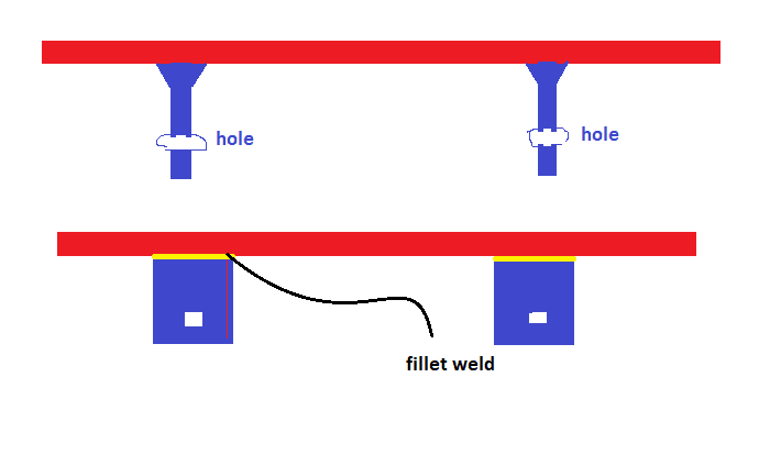
Does your suggestion looks like this?
Steel_plate_for_hook_sfqb23.png
 
NewbieInSE:
That’s the general idea, but I don’t understand the square holes or the two pin pls. I would have one of my lifting devices at each of your lifting loops, 1031mm (40.6”) apart. Can your slab and structure take 6 tons that close together? The vert. stl. pl. might be 4 or 5” wide, by 1” thk., by 10 or 11” long, with a drilled 1” dia. hole about 2.5” below the bot. of the conc. slab. The 1” thk. and the 1” dia. pin hole will pretty much match a 3 or 4 ton shackle. You should supply the shackle, with a cotter pin through the shackle pin, and just leave it hanging on the pin pl. The vert. stl. pl. is fillet welded to the underside of the stl. pl. in the top of the conc. slab. Remember, there can be some lateral loading on these pin pls. too. You lifting eyes could be as simple as some closed eye ‘eye bolts’ welded to the underside of the stl. pl. above, or they could be through bolted with nuts and washers t&b. You determine the sizes, welds, etc.
 
It's being hard for me to visualize, a sketch would be helpful, dhengr. However, thank you for your kind effort.
 
NewbieInSE:
They are just a ‘tee’ shape, like a lifting pad eye on any piece of equipment, one at each of your lifting loops. A steel base pl., maybe 6 or 8” sq. and .75” thk., with the 1” thk. web pl. welded to the base pl. with a couple fillet welds. You weld this all downhand and then flip it over 180° so the web is hanging down through the bottom of the slab form, and the top of the base pl. matches the top of slab elevation. You have to design all of this depending upon your exact conditions. The web pl. is maybe 5 or 6” wide and stands about 11 or 12” high when welding, that is; (6” slab, minus .75” base pl. thk.), plus 5 or 6” below the slab for a shackle and pin hole, with a proper edge distance, and finished shape, for the lifting loads. See ASME BTH-1, latest ed., “Design of Below-the-Hook Lifting Devices” for this part of the design. There are two of these, one for each of your lifting loops, 1031mm apart. Add a few pieces of rebar around them to control cracking where the web pl. pierces through the bottom of the slab. This rebar will also act to confine the slab from the punching shear standpoint. The thk. of the web pl. is intended to match the shackles you will need for your loads and FoSs, as are the pin hole size and web pl. end shape, etc., to work with the shackles or other lifting hardware. I can’t seem to scan things these days with the computer and printer combo. I have so sketches are tough for me. Read my posts again, vary carefully, and draw a sketch of what you are reading, I am trying to draw you a word picture with my descriptions/explanations.
 
dhengr, it's clear now. I understood your last response very well. It had been very informative, dhengr. Thanks a lot.
 
Status
Not open for further replies.

Part and Inventory Search

Sponsor