Continue to Site

Eng-Tips is the largest engineering community on the Internet

Intelligent Work Forums for Engineering Professionals

  • Congratulations waross on being selected by the Eng-Tips community for having the most helpful posts in the forums last week. Way to Go!

Wood Shear Wall on Concrete Podium Design

Status
Not open for further replies.

Yao1989

Structural
Jul 10, 2014
64
I got a question. I am adapting ASCE 7's two-stage seismic analysis for the canadian code to design mid-rises. My first time doing a project like this where seismic governs.

According to ASCE 7, I understand I am suppose to scale up the reaction from wood to concrete by RdRo wood (3.0x1.7) / RdRo concrete (1.5x1.3) (Rd/rho in ASCE, RdRo in canadian code). However when it comes to the tension/compression caused by the hold-down, some have suggested to me that the tension/compression only need to be scaled up to the capacity of the ATS rod (e.g. 12~1.4) instead of ratio of RdRo wood / concrete (2.6). I suspect scaling up the Tf Cf by 2.6 would result in very uneconomical design that is not common practice.

I am curious to what others have done in this scenario. Much appreciated.
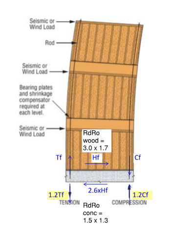
woodwallonconc_cq02kf.png
 
Replies continue below

Recommended for you

Capacity design seems all well and good but you'll need to find the expected capacity of the ATS rods, not the published capacity, which is already properly reduced.
 
Good point.

Another point to consider is that in most cases for ATS embedded in concrete is that concrete breakout usually govern, and we have to specify mustache bars to reinforce the breakout cone, which is expected to be the "weak-link" in the load path. Given the mustache bar is typically 400W here in canada, and as per G30.18 requires maximum yield strength of 525MPa, minimum 400MPa, I suppose I can assume the breakout cone to be close to the holddown anchor strength?
 
I have nothing productive to add but I did want to say that I practice in Ontario and I have not once heard of the term 'mustache bar'. It will now be standard fare on all my drawings. I very much appreciate the call-out
 
I think it has to be detailed to ensure that it behaves that way.
For heavy hold-downs of this sort I've often detailed them to extend all the way through to the underside of the slab and provided them with a big fat bearing plate. Then you're really just designing for punching shear. If you're on top of a wall I'd consider hairpins or localized vertical bars or something of that sort to ensure you meet your anchorage requirements.
 
Also, note that in this case the capacity design approach would only make sense for the tension aspect of the hold down.

Flip through the wood design handbook and see what provisions there are for factoring of seismic connection forces. I don't have my copy on me at the moment, but I seem to recall they allow a 20% increase over design loading for connectors, etc. There may be some additional conditions.
 
Atrizzy:
RE: your 24Aug, 16:37 post: Doesn’t the large underside bearing pl., nut, ATS rod, etc. become a fire rating, and fire cover issue, in the garage below?
 
dhengr, apparently not as the architect was fine with it and allowed the firespray to go directly over top.
 
Enable said:
I have nothing productive to add but I did want to say that I practice in Ontario and I have not once heard of the term 'mustache bar'. It will now be standard fare on all my drawings. I very much appreciate the call-out

I'm not sure I have anything productive to add either. Are your mustache bars shaped like these?

[URL unfurl="true"]https://res.cloudinary.com/engineering-com/image/upload/v1629835709/tips/mustache_bars_bynn7h.pdf[/url]

BA
 
You should check out THIS DOCUMENT and skip to Appendix E (page 64). It goes through a mid-rise example with the ATS system and designed around NBCC 2015 and CSA O86.
 
I am not sure why you would delve into ASCE for this given the APEGBC document. Simpson offers free design of the ATS system by the way.
 
Thanks for all the feedback.
I've gone through the example calculation previously, and found it completely very wood focused, and did not discuss much about when we can assume concrete podium is stiff, which is why I need to go into ASCE to understand when 2-stage analysis is applicable.

For the purposes of Clause 4.1.8.9.(1) of the BCBC height limits (m), the SFRS height shall be taken as the vertical distance from the ground floor to the center of mass of the roof. For sloping ground floors, the average elevation should be taken. Note: This definition is based on the assumption that any structure below the ground floor is a concrete box with stiff walls on all 4 sides.


I've however looked over again, and found this sentence in that document; so it seems like this is the answer I was looking for:
m) For wood framed structures supported on a suspended concrete structure, the connections for shear and moment between the wood frame shearwalls and the concrete slab shall be subject to full capacity design. This means that moments and shears applied to the supporting structure shall be based on capacities determined with w = 1.0 and s = 1.25.

I believe this is the most definitive answer I can find about what forces to design for the concrete.
 
Status
Not open for further replies.

Part and Inventory Search

Sponsor