-
1
- #1
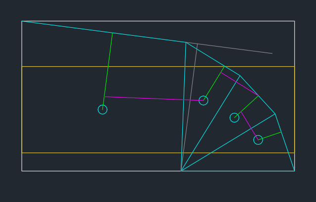
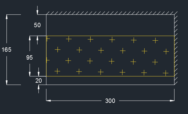
I recently had to find the capacity of a rectangular steel plate (300 x 165 mm), rigidly clamped along two edges as shown in the picture below. It is a 25 mm thick plate with yield strength of 250 MPa. The yellow hatched area is a rubber bearing pad which applies a uniform pressure onto the plate. I should point out that while this looks like a homework problem, it is a real steel bracket that I have been asked to review. There are other components of the bracket that I have left out for simplicity, but the clamped edge conditions are well justified in this case.
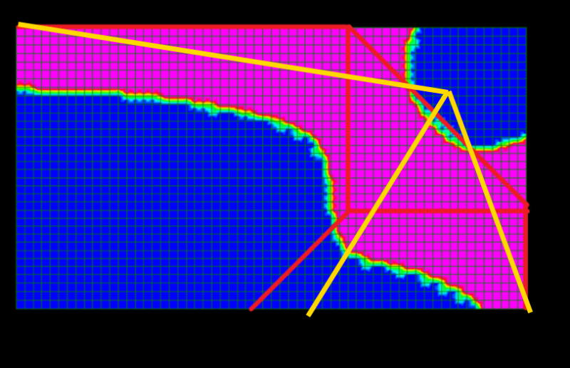
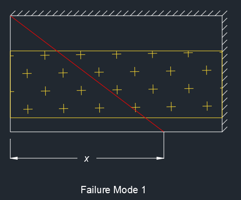
I could see two potential failure modes. The first (see below) was the corner of the plate folding downwards with some unknown dimension 'x'. I won't post my calculations here because they are lengthy and messy, but solving for minimum failure pressure yields x = 300 mm (i.e. the full width of the plate). This gave a pressure of 17.2 MPa over the bearing pad. The work done by each patch load was calculated based on the total force acting on the area multiplied by the deflection at the centroid of that area.
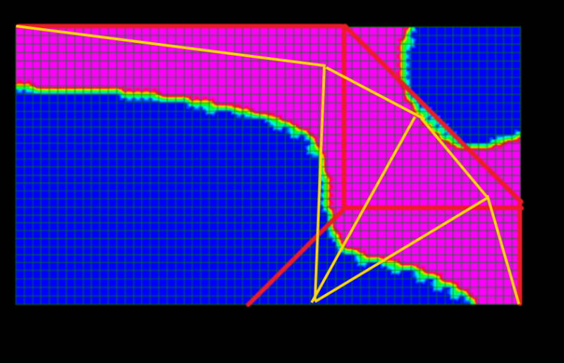
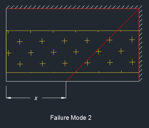
The other potential failure mode is shown below, with the plate yielding along the clamped edges and also diagonally, again with unknown 'x'. This was solved to give x = 136 mm, with basically a 45 degree angle for the diagonal yield line. Critical pressure is 13.6 MPa over the bearing pad, and therefore appears to be the most critical case.
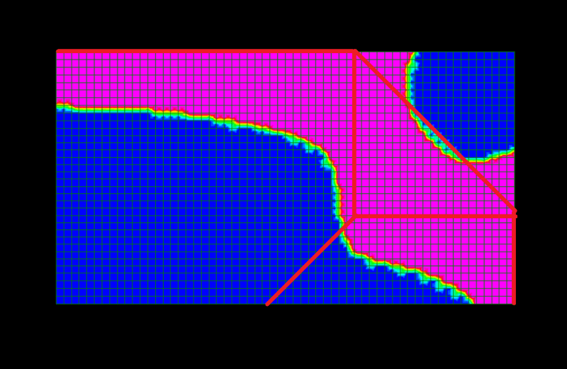
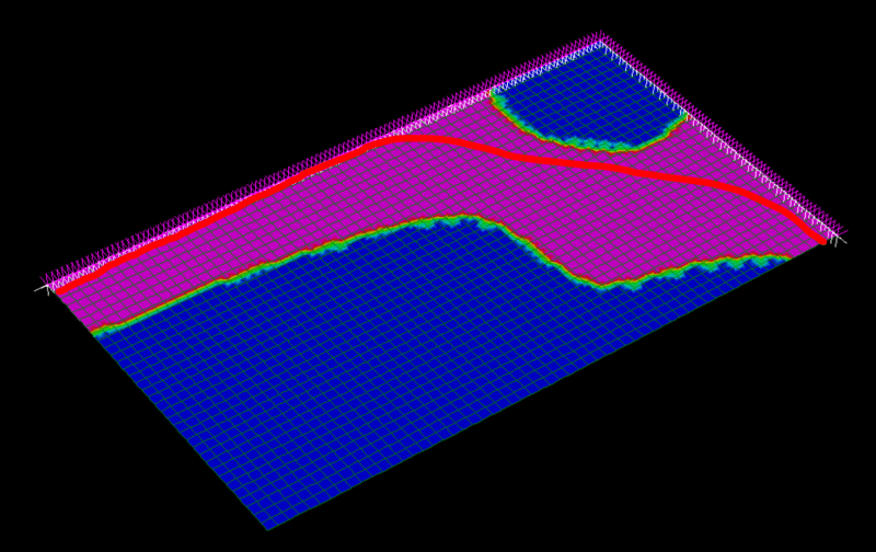
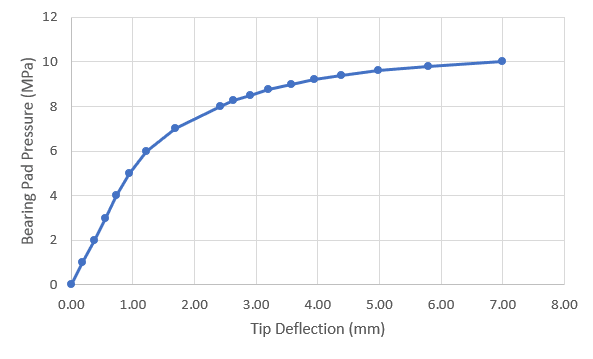
At this point I was satisfied that this would be the critical failure pressure on the bearing pad, but I wanted to confirm this with a nonlinear FE model. The failure mode predicted by the FE model is shown below. The pink regions indicate where the full plastic capacity of the plate has been reached. The limiting pressure appears to be about 10 MPa (roughly 75% of the predicted failure pressure based on the yield line analysis). What is immediately apparent is that the yield lines do not extend to the corner of the plate but gradually turn inwards and meet somewhere in the middle. There is also no obvious yield line in a diagonal direction. In fact much of the region in the middle remains elastic even after relatively large deflection. The FE analysis did not capture the post-peak behaviour because it was a load-controlled analysis. Possibly the peak pressure may have been closer to 11 MPa or so.
My question then is: how could this sort of failure mode be predicted by yield line analysis? I understand that yield line analysis is an upper bound method and therefore is no guarantee that the critical case has been checked; however, when there are potentially limitless failure modes to be checked, how can we be sure that we have selected the correct one? For simple cases like continuous beams, I can see that yield line analysis can be performed with confidence. But with plates, especially with irregular loading or support conditions, it seems that nonlinear FEA is the only way to be sure.
Any thoughts?

I could see two potential failure modes. The first (see below) was the corner of the plate folding downwards with some unknown dimension 'x'. I won't post my calculations here because they are lengthy and messy, but solving for minimum failure pressure yields x = 300 mm (i.e. the full width of the plate). This gave a pressure of 17.2 MPa over the bearing pad. The work done by each patch load was calculated based on the total force acting on the area multiplied by the deflection at the centroid of that area.

The other potential failure mode is shown below, with the plate yielding along the clamped edges and also diagonally, again with unknown 'x'. This was solved to give x = 136 mm, with basically a 45 degree angle for the diagonal yield line. Critical pressure is 13.6 MPa over the bearing pad, and therefore appears to be the most critical case.

At this point I was satisfied that this would be the critical failure pressure on the bearing pad, but I wanted to confirm this with a nonlinear FE model. The failure mode predicted by the FE model is shown below. The pink regions indicate where the full plastic capacity of the plate has been reached. The limiting pressure appears to be about 10 MPa (roughly 75% of the predicted failure pressure based on the yield line analysis). What is immediately apparent is that the yield lines do not extend to the corner of the plate but gradually turn inwards and meet somewhere in the middle. There is also no obvious yield line in a diagonal direction. In fact much of the region in the middle remains elastic even after relatively large deflection. The FE analysis did not capture the post-peak behaviour because it was a load-controlled analysis. Possibly the peak pressure may have been closer to 11 MPa or so.


My question then is: how could this sort of failure mode be predicted by yield line analysis? I understand that yield line analysis is an upper bound method and therefore is no guarantee that the critical case has been checked; however, when there are potentially limitless failure modes to be checked, how can we be sure that we have selected the correct one? For simple cases like continuous beams, I can see that yield line analysis can be performed with confidence. But with plates, especially with irregular loading or support conditions, it seems that nonlinear FEA is the only way to be sure.
Any thoughts?

