Continue to Site

Eng-Tips is the largest engineering community on the Internet

Intelligent Work Forums for Engineering Professionals

  • Congratulations waross on being selected by the Eng-Tips community for having the most helpful posts in the forums last week. Way to Go!

Moment connection considered pinned by Idea-StatiCa? 3

Status
Not open for further replies.

Logan82

Structural
May 5, 2021
212
Hi!

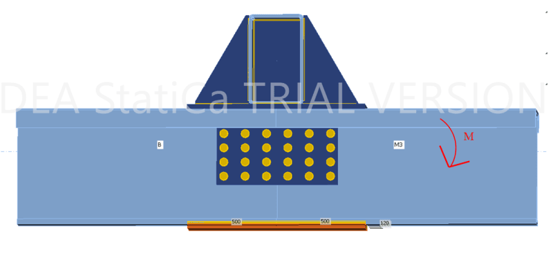
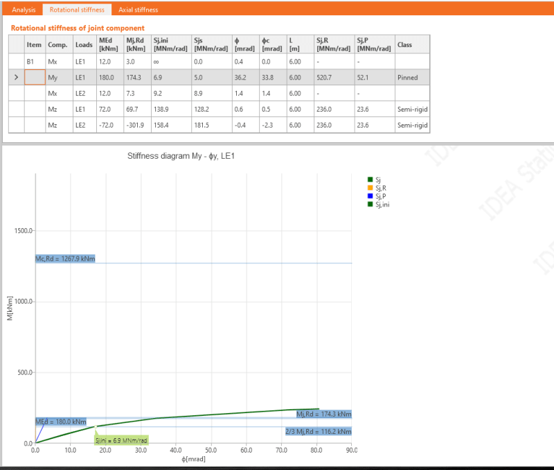
I have calculated a moment connection by hand. It must resist a moment of 210 kN*m. Everything works. However, when checking it in Idea-StatiCa, the connection is modeled as pinned. Would it still be legit to consider this as a moment connection? The classification of pinned vs semi-rigid vs rigid is based on Eurocode.
2021-09-21_10_16_00-Window_szoevl.png

2021-09-21_10_19_04-Window_fadi7o.png

2021-09-21_10_24_47-Window_hnhd7f.png
 
Replies continue below

Recommended for you

It's possible that the program is looking only at force rotation curves to determine moment vs pinned connections. Since you're connecting to a torsionally weak moment connection, that deformation curve is going to be pretty flexible.
 
I know that this connection is sufficiently resistant (it was also verified that the connection was sufficiently resistant in Idea-StatiCa). However from I understand, these are the consequences:
1) Since it is not very stiff, it will deform alot in rotation.
2) Thus, the issue will be that the infinite stiffness assumption of the moment connection in my Advande Design America model for the member calculation will be different from reality.
3) Hence, the forces will be spread differently in reality vs in my model.
 
Correct on all three. You did make sure the top flange bolts are all slip-critical in IdeaStatica, correct?
 
Yes they are slip-critical both in the model and in reality.
 
What if you relocate the beam splice? If you analyze your tube to beam connection without the splice below, does it perform any better? What about considering a beam splice away from your tube connection? Is there any flexibility in the design to rearrange things like that?
 
Anytime you put a wide flange member in significant torsion, then your frame analysis may become questionable. The reason for this is that torsional warping (which provides more stiffness than St. Venant's torsion) is not usually modeled in most FEM programs. Therefore, it would be my guess that (if your frame analysis is incorrect) then the issue is that it's more flexible than it would really be in reality.

But, that depends of a lot of things. Especially whether your FEM program considers torsional warping stiffness or not. Even if it does, how it handles it could be important too.
 
This is an evaluation of an existing structure, so I was trying to see if bracings would be required due to the flexiblity in the "moment connection". However I can't modify the connection.
 
My program does not consider torsional warping. However in this case, I don't see where there could be torsion in the wide flange beam. The HSS is in torsion, but the wide flange beam is in bending.
 
"I know that this connection is sufficiently resistant (it was also verified that the connection was sufficiently resistant in Idea-StatiCa). However from I understand, these are the consequences:
1) Since it is not very stiff, it will deform alot in rotation.
2) Thus, the issue will be that the infinite stiffness assumption of the moment connection in my Advande Design America model for the member calculation will be different from reality.
3) Hence, the forces will be spread differently in reality vs in my model.
"
If you have assumed infinite stiffness for member calculation and the connection design shows minimal rotational restraint, then you are right, and the actual mid-span (for example) values of bending moment in beams connected in this joint will be larger than your model predicts. The conservative estimate is to model your beam first as a pinned connection in the main model, design the span against that result, and then model it as a stiff (infinitely stiff) connection, and design the area near the joint according to that result.

A more elaborate solution is to assign a rotational spring constant in your main model, but if you do that, keep in mind that the range of "elastic joint stiffness" (linear or rotational spring stiffness) is not easy to pin down correctly: if zero stiffness means "k=0 kNm/rad", then a moment connection may require "k = 1000 kNm/rad" or "k = 10 000 kNm/rad" or "k = 100 000 kNm/rad", and it still may be nowhere close to attracting as much moment as an "infinitely stiff" connection.
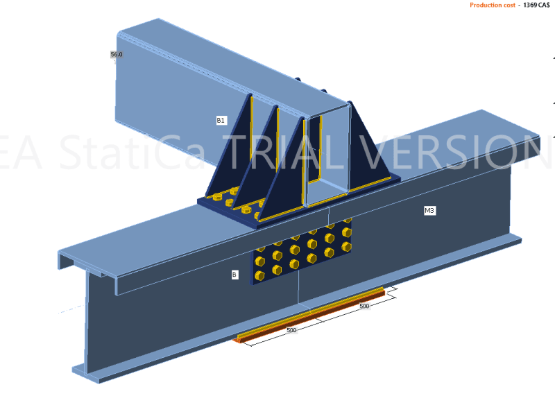
 
The beams in the mid-span are sufficiently resistant even with pinned connections.

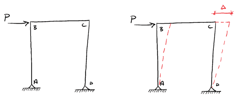
However, I am trying to make sure that the lateral stability of the moment frame is adequate, since it relies solely on those moment connections.

Bracing1-1024x423_sbmauq.png
 
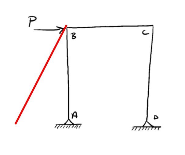
Or if it requires a bracing like this:
2021-09-21_12_18_00-Window_lzofu6.png
 
This is an evaluation of an existing structure, so I was trying to see if bracings would be required due to the flexiblity in the "moment connection". However I can't modify the connection.

Ahhh, that makes more sense to me now. I mis-interpreted the moment that was being transferred to the WF beam. Your frame analysis should be fine.
 
Finally, here is my rationale that bring me to think that a bracing is not required:

- There is a bracing in K on the other side of the frame:
2021-09-21_12_39_04-Advance_Design_America_-_190425-NLH-NEW-SSTR-R109_TEST4.vd1_ukhkro.png

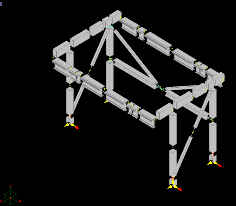
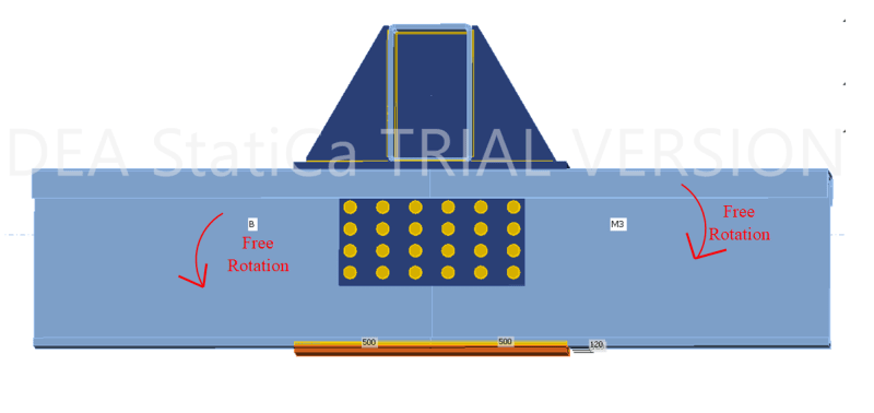
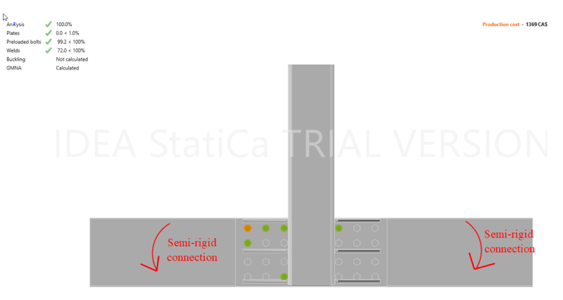
- By putting the connection as pinned (free rotation) in the direction in picture 1, it remains that the connection, which is semi-rigid in the direction shown in picture 2 according to Idea-Statica, is sufficiently strong to hold the lateral load so that the bracing in K can contribute on the other side of the frame.
Picture 1 (view from the front):
2021-09-21_12_45_09-Window_rti4kn.png

Picture 2 (view from the top):
2021-09-21_12_52_42-Window_hvnpde.png

- The beams are able to resist having pinned ends in bending around weak axis.
 
JoshPlumSE, would you still say that this is a pretty flexible moment connection?
 
It looks to me like you have done everything you can to make it as rigid as possible.

I'm not sure it's a "traditional" moment connection like we see with Beam to Columns. The classification that we see in AISC (or other codes) based on rigidity is most likely to apply best to beam / column moment connections.

The offset of the Tube from the wide flange makes this categorization a little trickier. I definitely wouldn't call it "pinned". So, semi-rigid might be the best way to term it.
 
Status
Not open for further replies.

Part and Inventory Search

Sponsor