Navigation
Install the app
How to install the app on iOS
Follow along with the video below to see how to install our site as a web app on your home screen.
Note: This feature may not be available in some browsers.
More options
Style variation
-
Congratulations MintJulep on being selected by the Eng-Tips community for having the most helpful posts in the forums last week. Way to Go!
You are using an out of date browser. It may not display this or other websites correctly.
You should upgrade or use an alternative browser.
You should upgrade or use an alternative browser.
TANK COMPRESSION RING AND RAFTER DESIGN
- Thread starter LAZAR90
- Start date
- Status
- Not open for further replies.
HTURKAK
Structural
- Jul 22, 2017
- 3,368
DEAR LAZAR90,
My points are,
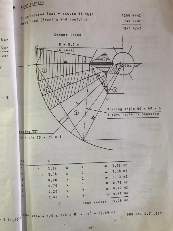
-The roof plan shows one purlin ring while the rafter has four point loads..The loads are only point loads but the rafter subject to continuous trapezoidal loading ..
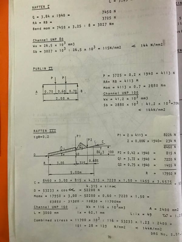
-The rafter subject to bending (which will govern for the design ) and shear forces while you have calculated only axial load.
-You did not provide bracing..
-The compression ring could be calculated using ROARK method. In general, circular angle ( made up of plates ) is used.
You may prefer to provide more details to get more specific replies.
- Thread starter
- #3
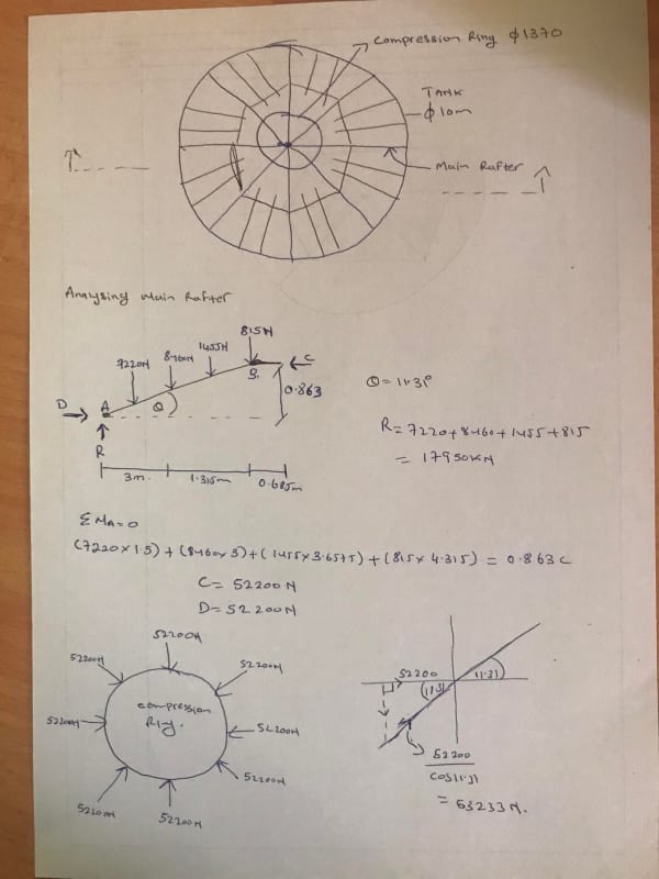
actually the rafter is subjected to trapezoidal load and i converted it to point load.
i want to know if am right
at point A there will be a horizontal force, D and resultant force, R.
at point B only horizontal force, C and NO resultant force, R
DOES THE FORCE 52200N ACTING ON COMPRESSION RING CORRECT
i want to know if am right
at point A there will be a horizontal force, D and resultant force, R.
at point B only horizontal force, C and NO resultant force, R
DOES THE FORCE 52200N ACTING ON COMPRESSION RING CORRECT
centondollar
Structural
"actually the rafter is subjected to trapezoidal load and i converted it to point load."
Where does this load come from? How will you "convert it into a point load" in practice? You will need an additional beam above the rafter, connected only to those discrete points, to provide load transfer from trapezoidal into point loads.
"at point B only horizontal force, C and NO resultant force, R"
That depends on the boundary conditions at the top of the compression ring.
"i want to know if am right "
You should ask someone at your office that question if you are unsure. Any advice you receive on an anonymous internet forum should be taken with a grain of salt - nobody here will provide you designs or definitive answers that you can use to prove (e.g., in court if something goes belly up during or after construction) that you did your due diligence.
PS. You can model this in a finite element software and compare your answers. They should be similar.
- Thread starter
- #5
On a 10m diameter tank, we'd normally use either a column-supported roof with single column and radial rafters, or a self-supported cone or umbrella roof (with no structure).
With the roof analysis shown, unbalanced loading becomes a problem to analyze.
With the roof analysis shown, unbalanced loading becomes a problem to analyze.
I don't know if I buy what you are doing because the forces at "A" is represented by a vertical and horizontal force. In reality, I would think (depending on how it is attached) there would be rotational restraint as well. (Which would [I think] impact forces.)
I would second that it is not the most economical option to use multiple layers of rafters for this size of tank. Why not just have rafters extending radially from a halo at the center of the tank with a single column? The current configuration just seems to add extra design time, construction cost, and maintenance issues.
I agree with LAZAR90's analysis. This setup is similar to a ladder on the wall of a house. No vertical load at the top of the rafter.
I checked by converting the calculated and given forces to the components parralell to and perpendicular to the longitudinal axis of the rafter. the axial forces sum to zero. conclusion - C is the resultant at the top of the rafter.
One other note - if there were vertical reactions at the upper ends of the rafters, then how would the compression ring handle those loads (what is supporting it)?
- Status
- Not open for further replies.
Similar threads
- Replies
- 31
- Views
- 16K
- Replies
- 4
- Views
- 10K
- Replies
- 4
- Views
- 633
- Replies
- 10
- Views
- 3K
- Replies
- 15
- Views
- 4K


