Continue to Site

Eng-Tips is the largest engineering community on the Internet

Intelligent Work Forums for Engineering Professionals

  • Congratulations waross on being selected by the Eng-Tips community for having the most helpful posts in the forums last week. Way to Go!

Spread footing overturn + uplift (Calculation vs Enercalc) 5

Status
Not open for further replies.

StrEng007

Structural
Aug 22, 2014
510
What is your approach to determining the factor of safety and the overall bearing stress for a spread footing subjected to overturning & uplift loads?
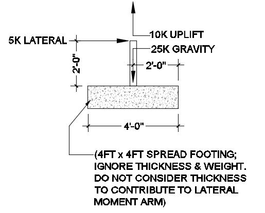
OT_rllqj8.jpg


Overturning Factor of Safety Check
Resisting Moment = 25k (2ft) = 50 k-ft
Destabilizing Moment = 5k (2ft) + 10k (2ft) = 30 k-ft
Overturning Moment FOS = 50 k-ft/ 30 k-ft = 1.67

Now, if you consider the resultant load eccentricity and the relationship, Overturn Factor of Safety = L/2e (where L if the footing length, 4ft):
e' = 4ft - (50k-ft - 30k-ft)/25k = 3.2 ft
Eccentricity, e = 3.2ft - 4ft/2 = 1.2 ft
Overturn FOS = L/2e = 4ft/(2 x 1.2ft) = 1.67, OK
When I calculate the bearing stress, my approach is, qmax = (2 x 25k) / [(3 x 4ft)(4ft/2 - 1.2ft)] = 5.20 KSF

However, if you enter the same criteria in Enercalc, you get approx. 1.875 KSF, achieved by:
e' = 4ft - (50k-ft - 30k-ft)/(25k - 10k) = 2.67 ft
Eccentricity, e = 2.67ft - 4ft/2 = 0.667 ft
Overturn FOS = L/2e = 4ft/(2 x 0.667ft) = 3.0, DOES NOT EQUAL 1.67
qmax = [2 x (25k-10k)] / [(3 x 4ft)(4ft/2 - 0.667ft)] = 1.875 KSF

My question is, what is the best way to handle the destabilizing uplift load? And why does Enercalc's method not maintain the relationship where OT FOS = L/2e ?
 
Replies continue below

Recommended for you

I am the author of that RISA document, though I no longer work there. I want to clarify some points about this calculation:
a) I didn't invent this calculation. Instead I fielded a call from a RISA user. Actually, my former boss (Ed) from when I worked at Fluor. He explained the method and why he thought it was better.

b) I did NOT like the proposal at first. I'd just always done the simple calculation where you look at the total axial force to determine the "stabilizing moment" even if some of that axial force came from wind or seismic. Plus, all the references I'd seen did the calculation that way.

c) But, as I was writing it up as a "user request" it just kept coming back to me..... That if you multiple your wind load by the "safety" factor, then you get a footing that is perfectly on the edge of overturning. Ed's words kept coming back to me. He'd said something like, "what is a safety factor supposed to mean?".

d) After spending more time with the concept and really thinking it through, I ended up changing my mind and really preferring that method. I had to "sell" this method to the other decision makers at RISA. That wasn't hard because by that time I'd really earned their trust when I really believed in a customer request. Eventually, we all were convinced that this the program needed to change to make this the only method that was used.

Over the next maybe 10 years, I probably talked to a dozen engineers who were upset that the RISA calculation was not giving them the same answer as a particular textbook or example problem. It would have been more if I hadn't done that write-up that StrEng007 linked to.

Of those dozen or so engineers, only one of them failed to accept the greater rationality of the "true safety factor" method.
 
JoshPlumSE, which of the two bearing pressures would you agree with? The 5.20 KSF or the 1.875 KSF? I don't have Risa to verify what the outcome would be.

Based on the relationship I've noticed with typical 'gravity' overturning moments, the OT FOS = L/2e. That being said, the 5.20 KSF would follow the same logic as you mentioned.

Enercalc doesn't show their method. I'm just trying to verify my results and as you said, a lot of time was spent thinking this one through.
 
Overturning Moment = 5*2 +10*2 = 30'k
Stabilizing Moment = 25*2 = 50'k
FOS against overturning = 50/30 = 1.67

Pressure on Footing:
Net vertical load P = 25-10 = 15k
Moment = 5*2 = 10'k (from horizontal force)

Eccentricity = M/P = 10/15 = 0.667'
Area footing = 4*4 = 16 ft^2
S footing = 4*4^2/6 = 10.667 ft^3
P/A+M/S = 15/16+10/10.667 = 1.875; P/A-M/S = 15/16-10/10.667 = 0
Thus, P acts exactly on the kern of the footing,
so the pressure varies linearly from 0 to 1.875 ksf.

BA
 
StrEng, your system would not be in equilibrium for your 5.2ksf case. You've included the uplift force to determine overturning moment but ignored it after that. The result is that you have (25+10)k up vs 25k down.

I haven't seen FOS=L/2e before but suspect it is based on the method of combining to a single resultant vertical force. If you use the actual eccentricity of 0.67' (per BAretired), you get FOS=3.0. Probably just a coincidence that it matched the other method when using the incorrect eccentricity of 1.2'.
 
I see what you're saying. For more typical cases where gravity and lateral are applied (no uplift), I've always noticed the relationship where the OT FOS = L/2e

Example, if you removed the uplift from this scenario:

OT Moment = 10 k-ft
Stabilizing Moment = 50 k-ft
FOS = 50/10 = 5

Eccentricity = 10k-ft/25k = 0.4
L/2e = 4ft/(2 x 0.4) = 5

When applying uplifting, I was trying to maintain this relationship between the OT FOS and the calculated eccentricty. The only way I could do that was to calculate the eccentricity at 1.2 FT. If you run any other scenario where you have applied moment and axial, I think the eccentricity and OT FOS honors the L/2e as mentioned.

What really threw me off is the latter yielded a FOS = 3.0, which aligned with the typical method mentioned in the first part of that Risa article I posted.
 
RISA said:
Older versions of the program could not handle situations where the Ultimate Level load combinations resulted in net overturning of the Footing. This is because the previous versions always relied on the soil bearing pressure calculations to derive the moment and shear demand in the footing. For net overturning cases, the current version of the program assumes that the design shear and moment can be based on the total vertical load and the net eccentricity of that load.

Josh, is this saying that RISA produces a design for an unstable structure? If so, what are the circumstances where ultimate load is applied but a stability check isn't required?

FWIW the true safety factor method would be closer to limit state design.
 
steveh49 said:
Probably just a coincidence that it matched the other method when using the incorrect eccentricity of 1.2'
Doesn't seem to be a coincidence. I checked some other scenarios and they all work out the same way. I suppose this goes back to the question, what is the true destabilizing moment vs the resisting moment?

If you take any other case with varying gravity loads and overturning moments as a result of an applied moment or applied lateral load, you'll see the relationship nicely ties into FOS=L/2e

Perhaps the uplift should not be counted as a force that destabilizes the system, instead, it reduces the applied 'resisting moment'. This would confirm the FOS = 3.0. If not, why are all the other cases able to be spot-checked by L/2e and not a case with uplift? It's just a simple relationship, no?

I'm not arguing either way. I appreciate your feedback!

 
The factor of safety against overturning is 1.5 for a 50% compressed footing and 3.0 for a 100% compressed footing. For rectangular footings, the kern is defined as "e < h/3" for 50% compressed footing area and "e < h/6" for 100% compressed footing area, where "e" is the eccentricity (vertical loads applied at COG, moment as a point moment at the COG, e.g., at the wall in the middle of the footing) and "h" is the length of the footing in the direction that overturning (moment) is to be resisted.

Proof:
50% compressed:
e > h/3
eccentricity of overturning moment:
e = M/P
---> M/P > h/3 ---> Mo > P*h/3
Resisting moment:
Mr = P*h/2
Ratio of resisting moment to overturning moment:
Mr/M0 = Ph/2 / (Ph/3) = 3/2 = 1.5.

Repeat for the 100% compressed case to acquire FOS = 3.0.

Not sure what all the fuss is about. Mind you, I didn't read through the thread with great attention to every last detail.
 
Repeat for the 100% compressed case to acquire FOS = 3.0.

That's the case in point. FOS=3 for this method. Now do limit state: the horizontal and uplift are wind load, the downward load is gravity (presumably dead weight).

Horizontal: 1.5*5k = 7.5k
Uplift: 1.5*10k = 15k
Downward: 0.9*25k = 22.5k

Overturning: 7.5k*2' + 15k*2' = 45k-ft
Restoring: 22.5k*2' = 45k-ft


FOS=3 gives you 1.5-1.67 capacity for increase in destabilising load, or <30% wind speed increase.

what is a safety factor supposed to mean?
 
The short answer is that the FOS = L/2e formula only works if the overturning force is entirely horizontal.

Calculating the FOS as (restoring moment)/(overturning moment) gives a FOS of 1.67 (as shown by BAretired)

I don't know where the bearing pressure of 5.2 KSF came from. Under unfactored loads the maximum bearing pressure is 1.875 (again see BAretired calcs). If the wind load is factored up by 1.67 the resultant vertical force passes directly through the toe, so the bearing area is zero and the stress is infinite.

Also I hope the weight and depth of the footing is just being ignored for simplicity in the example calculations.

Doug Jenkins
Interactive Design Services
 
steveh49:

You must choose between using factors of safety for loads combined with the equilibrium equation, or to use the eccentricity criteria (e < h/3 or e<h/6 for rectangular footings) with characteristic values for centric normal force (selfweight of footing and earth/structures above it) and overturning moment. The FOS of loads is directly embedded in the moment equilibrium (restoring vs. overturning), as you showed, and it has no relation to the theoretical (based on algebraic manipulation) 50%/100% kern results.

If you use FOS for the loading and employ the kern equation criteria, you will use factors of safety twice. It certainly is conservative and is probably often done, but it is not the most optimal solution.
 
In my view, the overturning moment = 5k * 2' = 10 k-ft
Stabilizing moment = (25k - 10k) * 2' = 30 k-ft.
FoS = 3.0
The uplift reduces the stabiling moment.

What would the factor of safety for overturning be on a foundation that has a gravity load of 15 kip with the same overturning moment of 10 k-ft. The bearing pressure diagram would be identical to the case that the OP posted, going from 0 to 1.875 ksf.

The FoS in that case is (15k * 2')/(10 k-ft) = 3.0. How and why should that be any different than a footing with a 25k downward load and a 10 kip uplift, which results in a net downward load of 15 kip?

This is an interesting thought exercise.
 
slickdeals said:
This is an interesting thought exercise.

Indeed it is. But if you increase the wind force by a factor of 2, then:

Overturning moment = 10*2 = 20
Stab. moment = (25-20)2 = 10 which means the foundation is overturning,
so can the FOS be as high as 3?

BA
 
I have never subtracted uplift from gravity and then calculated rotation. I have always treated them based on stabilizing or de-stabilizing. -25x2 and then 10x2 for example. One goes in numerator, one in denominator.

Even though I treat uplift as if it can create overturning in either direction, I still think that something seems wrong with that. I understand the application of statics states it does. For a given free-body diagram, a vertical uplift that is "centered" can cause and equal but opposite, positive and negative rotation simultaneously? I can see the gravity load acting that way. You can test that theory by lifting something from one end, and then trying the other end. For a symmetric situation, it is as hard one way to rotate than it is the other. The difference is, you are actually creating overturning each time by lifting at the outer edge. Gravity resists the overturning from lifting in the anti-gravity direction. These uplift loads are centered, not at the edge. I always design for uplift first (summation in the Y). Once my footing works for that, I get into overturning. It is a metal building habit. For PEMB footings in non-snow areas, I do DL+LL last.
 
Moment 10Kft, Axial Load 15K, e = 10/15 = .666666'
kern 4'/6 = .6666'

Bearing = 15K/16sqft = 1ksf X 2 = 2ksf max...

OK, just a matter of checking overturning factor...

Rather than think climate change and the corona virus as science, think of it as the wrath of God. Feel any better?

-Dik
 
RISA said:
Older versions of the program could not handle situations where the Ultimate Level load combinations resulted in net overturning of the Footing. This is because the previous versions always relied on the soil bearing pressure calculations to derive the moment and shear demand in the footing. For net overturning cases, the current version of the program assumes that the design shear and moment can be based on the total vertical load and the net eccentricity of that load.

Steve49 said:
Josh, is this saying that RISA produces a design for an unstable structure? If so, what are the circumstances where ultimate load is applied but a stability check isn't required?

Those are two different levels of force. RISAFoot checks overturning and soil bearing for SERVICE level forces. Right? Then it designs the concrete footing for STRENGTH level forces.

That quote you gave from the RISA documentation is related to cases that were stable under service level loads. But, when you added in the Load Factors became unstable for strength level loads. When RISAFoot first came out, it always calculated the soil bearing pressure (under ultimate level loads) to come up with the shear and moments in the concrete slab. So, if your OTM stability ratio (for the ultimate loads) was 1.0, then you would have what was the equivalent of point load at the tip of the footing. But, if you had a infinitesimally larger level of moment then it would refuse to check the footing for moment or shear. Since that update, it treats those cases as a point load applied at the eccentricity location (at the factored / ultimate level load) in order to obtain Mu and Vu at various locations in the footing.
 
OP/StrEng007 said:
JoshPlumSE, which of the two bearing pressures would you agree with? The 5.20 KSF or the 1.875 KSF? I don't have Risa to verify what the outcome would be.

I don't have any RISA programs anymore either. I haven't run the numbers for your program either. I only spoke up to explain the rationale behind that RISA article that was cited by the other poster.
 
I'm with Ron/RISA and believe any other method is incorrect. I would say codes are prescriptively in agreement with splitting vertical stabilizing and destabilizing loads, as if you assess stability of the footing under LFRD combinations, you get the true FOS (0.9D+1.0W for ASCE 7, but with a 1.67 factor baked into the wind loads, and likewise for NBC, 0.9D+1.4W).
 
Status
Not open for further replies.

Part and Inventory Search

Sponsor