Dear engineers,
For a couple of years I visited many times your “EngTips” site for a fresh look on piping issues. I am a design engineer on retirement and spent about 35 years in engineering firms and construction sites. Nowadays I spent some times to study subjects related to piping I never had the time for that. Such a subject is the comparison between ASME en EuroNorm flanges (see Flanges comparison).
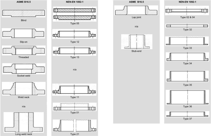
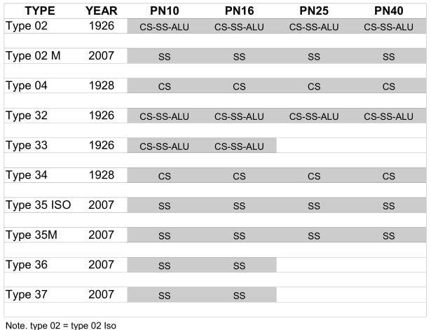
There are four columns for the geometric comparison between ASME and EN. In the 3rd and 4th column are the lap joints and stub ends. The EN has more of these items to choice. Type 02 & 35 consist of ISO and metric design (metric version is not shown in 4th column). Why some many designs in the EN norm? So I asked myself the next question:” if I don't have a pipe spec, which flange would I choice for a good design”?
So, I did study all the facets of flanges and makes a report (in Dutch) of it. My approach has been of a qualitative nature to still get results on the pro & cons in the engineerings phase and operational phase.
This report is 14 pages long and unfortunately is takes to much time for me (now this moment) to translate it.
Some points I will highlight:
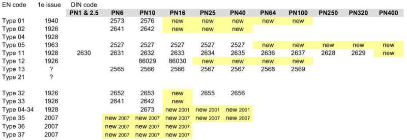
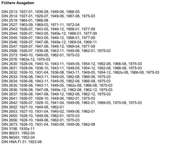
-In DIN period (from 1928 to 2007) only the PN10 range of type 04-34 consist,
-After 2001 (harmonization DIN to EuroNorm) PN16 to PN40 are added,
-Some of the dimensions of the welding neck flange are taken over,
-There are no re-calculations made on the new type 04-34.
-There is only one firm in Europe who is manufactured this type (I did sent the report to them and hope on response).
One of the thinks I discovered was the integrity of flange type 04-34 of the EN 1092-1(see fig.A&B).
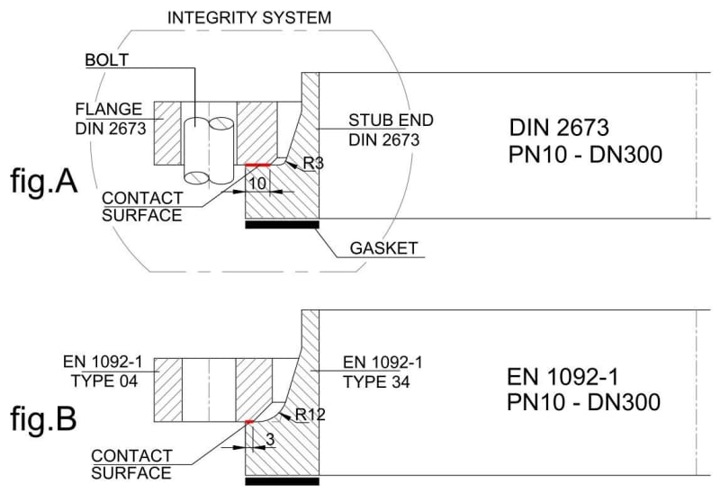
In fig.A you can see the old DIN flange assembly. Fig.B gives the new release of PN10 range. You can see the decrease in contact surface. If the tolerances are “counteracting”, the ring of 3 mm will be 2 mm. I don't have to tell what happens if there is some misalignment or water hammer in the system.
The same goes for the whole diameter PN10 range:
-DN15 to DN200, ± 30% less contact surface
-DN250 to DN600,± 60% less contact surface
Because in the old DIN 2673 only the PN10 range existed there is no comparison for the PN16 etc.
I am aware of this EuroNorm treatise in the ASME bastion![[bigsmile] [bigsmile] [bigsmile]](/data/assets/smilies/bigsmile.gif) .
.
So, and now finally my question to you: Do I have a point if my conclusion is that this construction is a bad design?
For a couple of years I visited many times your “EngTips” site for a fresh look on piping issues. I am a design engineer on retirement and spent about 35 years in engineering firms and construction sites. Nowadays I spent some times to study subjects related to piping I never had the time for that. Such a subject is the comparison between ASME en EuroNorm flanges (see Flanges comparison).

There are four columns for the geometric comparison between ASME and EN. In the 3rd and 4th column are the lap joints and stub ends. The EN has more of these items to choice. Type 02 & 35 consist of ISO and metric design (metric version is not shown in 4th column). Why some many designs in the EN norm? So I asked myself the next question:” if I don't have a pipe spec, which flange would I choice for a good design”?
So, I did study all the facets of flanges and makes a report (in Dutch) of it. My approach has been of a qualitative nature to still get results on the pro & cons in the engineerings phase and operational phase.
This report is 14 pages long and unfortunately is takes to much time for me (now this moment) to translate it.
Some points I will highlight:
-In DIN period (from 1928 to 2007) only the PN10 range of type 04-34 consist,
-After 2001 (harmonization DIN to EuroNorm) PN16 to PN40 are added,
-Some of the dimensions of the welding neck flange are taken over,
-There are no re-calculations made on the new type 04-34.
-There is only one firm in Europe who is manufactured this type (I did sent the report to them and hope on response).
One of the thinks I discovered was the integrity of flange type 04-34 of the EN 1092-1(see fig.A&B).

In fig.A you can see the old DIN flange assembly. Fig.B gives the new release of PN10 range. You can see the decrease in contact surface. If the tolerances are “counteracting”, the ring of 3 mm will be 2 mm. I don't have to tell what happens if there is some misalignment or water hammer in the system.
The same goes for the whole diameter PN10 range:
-DN15 to DN200, ± 30% less contact surface
-DN250 to DN600,± 60% less contact surface
Because in the old DIN 2673 only the PN10 range existed there is no comparison for the PN16 etc.
I am aware of this EuroNorm treatise in the ASME bastion
![[bigsmile] [bigsmile] [bigsmile]](/data/assets/smilies/bigsmile.gif) .
.So, and now finally my question to you: Do I have a point if my conclusion is that this construction is a bad design?

