Continue to Site

Eng-Tips is the largest engineering community on the Internet

Intelligent Work Forums for Engineering Professionals

  • Congratulations waross on being selected by the Eng-Tips community for having the most helpful posts in the forums last week. Way to Go!

Steel Brace Fabrication Error Question

Status
Not open for further replies.

sticksandtriangles

Structural
Apr 7, 2015
472
I have a condition where due to a fabrication error, a very heavily loaded brace now has a 1" gap between the typical flange plate connection and the brace itself.
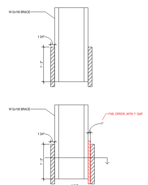
image_1_tdqa72.png


The contractor is asking us if a shim plate can be used to fill the 1" gap (see red shim plate) to prevent ripping it out and starting anew.
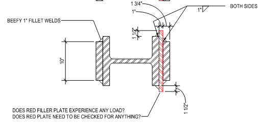
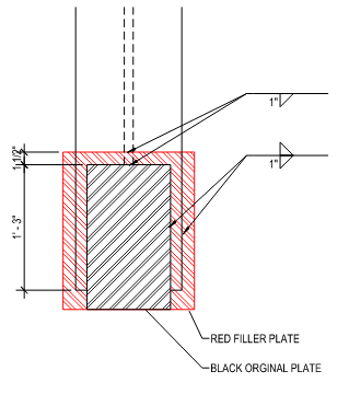
image_2_asfgji.png

image_3_awnmwx.png


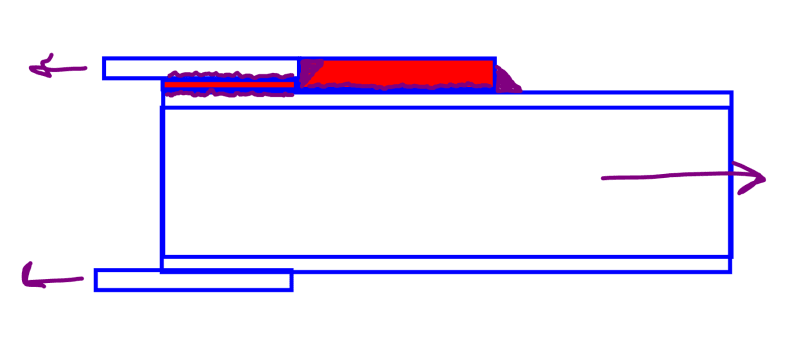
The load in the brace flange needs to flow into the shim plate and then transfer the load into the original brace flange plate. We have a very big 1" fillet weld connection in the original design on (3) sides of the plate. Does this red plate need to have any sort of strength? It feels like the load path is quite direct, in that the plate never goes into shear or tension and the load "flows" from one weld to another, with the plate just providing a welding surface to make the flow happen. Is there anything I should be checking on the shim plate?

Appreciate the feedback!

S&T -
 
Replies continue below

Recommended for you

I'm curious how load "flows" through a material without inducing shear (direct or torsional) stresses or normal stresses (axial or flexural). It will absolutely need sufficient strength to transfer the load. Draw a FBD of the entire connection filler plate and you'll see the load path and can design it accordingly.
 
For a 1" plate the max weld size is 15/16". This applies to the bottom figure, top weld.

I would check the red plate for block shear. The strength will be high, but you said "very heavily loaded" and it's just over half as thick as the 1.75" plate that the original bdesign is based on.
 
What is the magnitude of the load and the dimension of the W section? If you can develop the force with 15/16 weld by increasing the size of the plate, I wouldn't normally worry about the fix, the added eccentricity is relatively small.

Rather than think climate change and the corona virus as science, think of it as the wrath of God. Feel any better?

-Dik
 
I think that you'll be fine with this. There's some tension lag, in theory, but the welds on the two faces of the filler plate are so close to one another that won't add up to anything appreciable. Ditto for the added eccentricity in the plane of the brace web. pham's right that there will be some short lived shear in the filler plate. You can check that easy enough but, realistically, it will probably be a non-issue given that you'll have already checked your weld for base metal shear failure.

 
concur KootK... about a 10 pass weld?

Rather than think climate change and the corona virus as science, think of it as the wrath of God. Feel any better?

-Dik
 
For what it's worth, AISC doesn't give an approximate number of passes for fillet welds larger than 3/4" (which is 8 for a fillet weld, so you're probably a bit light on your estimate, dik). That would give me pause before specifying a weld that large. I have a document somewhere that goes into detail on special consideration for welding thick plates - if I find it I'll post it.

KootK- I'm not so sure that it'll be a non problem given the OP's original suggestion that the load will "flow" without causing shear. What kind of steel is that plate made from? For A36, a quick back-of-the-napkin check suggests base metal shear controls over weld size for a 1" thick filler. That means that eccentricity between the welds on either side may not be so trivial.


It's OK... it was a WAG and I was just trying to be humourous. [pipe]

Rather than think climate change and the corona virus as science, think of it as the wrath of God. Feel any better?

-Dik
 
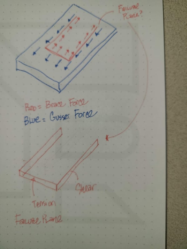
FBD of the shim below, I guess I see a sort of block shear plane that needs to be accounted for.

20220121_150235_mmpxiq.jpg


The fun grows now with contractor stating that they can only allow for a 1/2" plate in the shim location.

Dik said:
What is the magnitude of the load and the dimension of the W section?
Load to be transferred through the gusset and through the shim is ~ 800 kips. Shape is a W12x190

271828 said:
For a 1" plate the max weld size is 15/16". This applies to the bottom figure, top weld.

Good call, missed that on the first pass. All made worse by the reduced plate thickness mentioned above.

phamENG said:
What kind of steel is that plate made from?

We were planning on 50ksi plate, but at 1/2" max plate, the block shear strength of the failure plane I drew is about 650 kips ultimate, not enough.


S&T -
 
eccentricity would be negligible for that size section IMHO. Use whatever size plate you need to 'fill the space'. Space permitting, it's just a matter of designing the weld for the loading... there should be no issues. If a field weld, with lots of passes, you might want to check the welds.

Rather than think climate change and the corona virus as science, think of it as the wrath of God. Feel any better?

-Dik
 
It occurred to me on the original design that you could make the spacer plate narrower than the outer plate by whatever amount desired, then fill the gap on either side with weld metal (IE, a wide butt weld with the spacer just acting as a backup). I don't suggest that's a good way to do things, just another possibility to consider. The 1/2" plate requirement makes that more attractive. If the assembly was loose where they could rotate it, that would help, too.
 
If it's only 1/2" that might be good. Do you have access to D1.1? What's the allowable root opening for a fillet weld?

Edit: Sorry - I think I typed that response on my phone and it changed fillet to filled.
 
A 1/2" Gr.50 PL won't work for J4 base metal checks. I would also not advise on trying to consider the gap as a CJP or PJP, the weld is not through the thickness of either joining member.

There are likely alternative solutions, though moving the flange plate to it's intended position seems like the best option.
 
phamENG said:
KootK- I'm not so sure that it'll be a non problem given the OP's original suggestion that the load will "flow" without causing shear. What kind of steel is that plate made from? For A36, a quick back-of-the-napkin check suggests base metal shear controls over weld size for a 1" thick filler. That means that eccentricity between the welds on either side may not be so trivial.

That's precisely why, in my original response, I mentioned that it was probably okay so long as the base metal check had passed. I'd taken that as given since I know a fair bit about S&T's capabilities. Given that the welds are practically on top of one another, I feel that the satisfaction of the base metal check probably also covers block shear. It certainly wouldn't hurt to check both, however, given the stakes.

phamENG said:
That means that eccentricity between the welds on either side may not be so trivial.

When I said that the effects of eccentricity would be trivial, I meant that in the conventional sense: that the eccentricities should not induce moments into the system that would require any great effort -- or even explicit attention -- to deal with. And I stand by that. If your point regarding the eccentricity was, rather, that the there would be some shear passed around owing to the fact that the welds don't occupy the same, literal space then, yeah, I agree of course.
 
I've pitched an alternate option below. In a non-seismic application, this would be good to go I think. I suspect that this is a seismic application, however, so one would have to find a way to do this while:

1) Retaining the joint's prequalification if it has one.

2) Not introducing fracture mechanics issues with backer plates, partial penetration welding etc.

3) Not substantially altering where plastic hinges would develop in the brace if such hinges are necessary to the program.

I'm not sure that what I've shown below actually accomplishes all of those things so be sure to do your own research.

c01_go8jry.png
 
phamENG said:
What's the allowable root opening for a filled weld?
Reading AWS, it appears to be 3/16" max for my situation. No dice there.

FYI, this is a non seismic application.

I'm leaning towards telling them to rip and replace.

Thanks for the sketch Koot, seems like a viable solution.

S&T -
 
Can you shim it both sides? This would somewhat even up the load distribution and maybe get you to within you root opening tolerances.

Honestly, I find the whole arrangement a little unsettling for an 800k connection force.
 
JLNJ said:
...Honestly, I find the whole arrangement a little unsettling for an 800k connection force.

That's what I keep thinking as I read this thread. We get so used to regular sized forces. The plates and welds look large, but they might not be. If it was 80 kips, I might mess around trying to come up with a slick way to fix it easily.

sticksandtriangles said:
...I'm leaning towards telling them to rip and replace. ...

For that level of load, if my seal was going on it, I'm 95% sure that's what I'd do. This doesn't seem like the connection to be super concerned with ease of fixing the mistake.
 
How is it misaligned at the base?
I would be worried about this geometric error chasing its way through the structure and through your load path
Given its heavily-loaded nature I'm more inclined towards ripping it out, but perhaps a compression + bending check being <<1 utilisation could reassure you of its suitability
 
Status
Not open for further replies.

Part and Inventory Search

Sponsor