Continue to Site

Eng-Tips is the largest engineering community on the Internet

Intelligent Work Forums for Engineering Professionals

  • Congratulations KootK on being selected by the Eng-Tips community for having the most helpful posts in the forums last week. Way to Go!

LTB mode with tension-compression bracing 4

Status
Not open for further replies.

Italo01

Structural
Sep 4, 2021
169
Hello,

If i have two Beams with Tension-Compression bracing, what preventing them to buckling laterally to oposite sides. I see that the point of contact of the two bracing bars move for this failure mode, so a bolt connecting the two bars would be the only thing preventing this type of failure? If it is, how to determine if this bolt is adequate?

Thank you.
 
 https://files.engineering.com/getfile.aspx?folder=ac9c7b65-d504-4519-8ada-de1e7f75877e&file=Bracing.jpeg
Replies continue below

Recommended for you

I think you're on the right track. For the sketched setup, you would need to add horizontal members to make the bracing system into a little truss.

In the AISC Specification, this subject is covered in Appendix 6. Also, check out the various beam bracing articles by Yura and Helwig over the last 20-25 years.
 
Thank you 271828.I did study article written by Yura called "Fundamentals of beam bracing" and regarding the horizontal members he describes this system called compression-tension system that does not uses horizontal members. When both beams tend to buckle to the same direction, one diagonal goes into compression and the other into tension, resulting in the moment necessary to restore the equilibrium.
 
I see that the bolt would prevent the moevment but cannot see how the forces would flow to create the moment in order to calculate the forces on the bolt. Does someone identifies?
 
I'm throwing this thought out there.

The system can be thought as symmetric about the bolt (split in along the vertical plane with the bolt as a fixed pin in space.) Resolving the required lateral restraint forces are then easy. If your top flange requires 1kN of lateral (horizontal) restraint as per code then that will impose 1kn on the fixed pin. Likewise if the bottom requires 1kN of lateral restrain.

So the total shear on the bolt is the sum of these. eg 2kN


Well I checked my thought experiment before I posted using my favourite lazy engineer use of software and the answer computer is exactly that. The angle of the cross braces doesn't change the net shear on the bolt.
 
Thank you human 909, i was thinking this way and your idea of using symmetry really helped.
 
The braces need to have adequate strength and stiffness to brace the beams. The tension brace is not as much of a concern since it will not fail by buckling. As mentioned above, Appendix 6 of AISC has good guidance on the strength and stiffness requirements. It does not take a very large force to brace the beam. You may be able to get away with a single bolt connecting the brace to the beam, but I like to use 2 bolts minimum, it provides redundancy and its cheap insurance.
 
While I would connect the angles nominally in practice, I don't believe that there is a practical, theoretical requirement for them to be connected. The buckling mode that you sketched forces pure torsional buckling in the beams with no lateral sway at all. Particularly for deeper beams, such as the kind that would be braced this way, pure torsional buckling capacity is quite high. I believe that this is why Yura's treatment of the scheme addresses only twin girder buckling modes that involve both beams rotating the same direction. Moreover, if one were to attempt to brace the beams for pure torsional buckling, those brace forces would likely be higher than those proposed by Yura which, I believe, are intended for a lateral torsional buckling mode involving significant sway.

human909 said:
Well I checked my thought experiment before I posted using my favourite lazy engineer use of software and the answer computer is exactly that. The angle of the cross braces doesn't change the net shear on the bolt.

I'd be curious to know how you did that. It seems to me that you've attempted to apply lateral bracing concepts to what is, fundamentally, a torsional bracing system (I think). I see a symmetric, half model of the system as I've shown it below. That would involve flexure in the angles and the determination of the bolt force would be a more complex thing involving both the geometry of the bracing and the stiffnesses of the bracing members. Something like some 3EI/L models on the braces and determining the vector sum of the accompanying shears.

c01_xbp3xc.png
 
Hey Kootk,

I think we are running into the same problem of thought difference as that fly bracing thread. You are seeing that the bracing is suitable and chasing up the most likely buckling load and considering that. Italo01 and I are a step behind and asking IF the bracing is suitable. The calculation of the require shear strength of the bolt is part of this process.

Kootk said:
The buckling mode that you sketched forces pure torsional buckling in the beams with no lateral sway at all.
I see a whole lot of lateral sway. You are looking at the entire system as a group, I'm still looking at individual beams. We can't consider the system until we examines that the beams are stiffly enough connected.

Kootk said:
I don't believe that there is a practical, theoretical requirement for them to be connected.
Absolutely there is. Without them being connected the they don't offer LTB restraint as the beams can LTB in mirrored unison. (as the diagram shows)

Kootk said:
I'd be curious to know how you did that. It seems to me that you've attempted to apply lateral bracing concepts to what is fundamentally, a torsional bracing system (I think).]
Yes. I was going down codified path where strength requirements of 2%/2.5% of flange force is required to presume a restrained flanged. I chose this approach because it fits the code and I presume it was the sort of answer desired. (Naturally, as we both know the restraint requirements are more about stiffness than strength but this is the code we have and we were looking for a path to determine a suitable bolt design load.)

In the half system thought model the 'bolt' doesn't have rotational restraint. In the quick computational model I did I did a 2D model of both the beams and braces. The shear forces in the bolt were as described.
 
human909 said:
Italo01 and I are a step behind and asking IF the bracing is suitable. The calculation of the require shear strength of the bolt is part of this process.

I also evaluated whether or not the bracing was suitable and, based on the theoretical argument that I presented previously, came to the conclusion that it surely is, even without the bolt. I assumed nothing.

human said:
I see a whole lot of lateral sway.

There's no sway in OP's failure mode. The braces force the top flanges to translate the same amount as the bottom flanges. The centroids remain stationary. That's pure twist, no sway.

Kootk said:
You are looking at the entire system as a group, I'm still looking at individual beams.

Not true. I also am looking at the individual beams. See the sketch of an individual beam that I posted earlier.

human909 said:
Without them being connected the they don't offer LTB restraint as the beams can LTB in mirrored unison. (as the diagram shows)

Without the connection between braces:

1) They brace the beams into behaving as one, torsionally compatible unit for twin girder, system LTB buckling. And that's precisely what Yura describes in the paper.

2) They brace the individual beams against lateral torsional buckling failure modes in the sense that the "lateral" part of that is precluded.

3) They do not brace the individual beams against a purely torsional buckling mode. But, then, that's a higher energy buckling mode than is LTB. So much so that I suspect that it's often irrelevant.

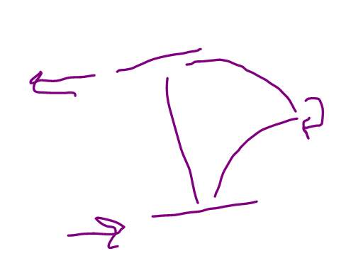

 
human909 said:
In the half system thought model the 'bolt' doesn't have rotational restraint.

The bolt doesn't have a rotational restraint but the joint must have a rotational restraint, as I showed in my sketch above. Otherwise, there's nothing to restrain twist of the half model under OP's proposed failure mode. I believe that you were on to this yourself in one of the comments that you deleted earlier.

deleted said:
Don't forget to size the cross bracing for the bending moments as well. While I don't have Yura's paper in front of me, there is more than just compression and tension happening in those cross members with this setup.

I believe that statement to be accurate.
 
Thanks for spelling it out to me KootK. What you say makes sense to me now. I can see the argument and why the bolt is likely not required. When I get a spare moment I might start the engine on some bulking analysis and get a few pretty pictures up for my own and anybody elses benefit.
 
You're most welcome human909. Thank you for the discussion and for reporting back to let me/us know that we've reached a consensus.

The next bit of the fun, for me at least, will be working up a formula for the bolt shear. Tentatively, this is what I've got:

1) Under OP's buckling mode, there actually is no axial force in the braces. Only shear and bending.

2) The bolt shear would be [2 x F / sin (theta)]. [F] being the lateral flange restraint forces and [theta] being the angle that the braces make with the horizontal.
 
Thank you KootK for your response. It makes total sense to me now why this mode of failure doesn't need to be considered. I think that it was so clear to Yura that he didn't even think of talking about, but i could not design the bracing without understanding this. I'm glad that i found Eng-tips.
 
You're most welcome Italo01, we look forward to your continuing participation here in our little community.

Italo01 said:
I think that it was so clear to Yura that he didn't even think of talking about..

That's my suspicion as well. Sometimes these gods of theory just don't waste any brain power on the "trivial" stuff that tends to trip up we mortals.

Do keep the one bolt at least.

 
If the braces are pinned to the beams and not connected at the crossing, how does the bending moment develop in them?

IIUC, Yura presumes that the tension flange provides lateral reaction to the brace as well as the vertical reaction mentioned in the article.
 
steveh49 said:
If the braces are pinned to the beams and not connected at the crossing, how does the bending moment develop in them?

I would say that it doesn't and that's part of why the setup would be ineffective for OP's proposed buckling mode in the absence of the bolt(s) or welds at the crossing. Even with a crossing connection, I feel that this scheme would be inefficient for resisting pure torsional buckling. It relies on the small-ish vector contribution of the braces being flexed into the beam to counter the flange restraint demand. In my mind, that adds credence to the theory that Yura never actually intended for the braces to do this particular job.
 
steveh49 said:
IIUC, Yura presumes that the tension flange provides lateral reaction to the brace as well as the vertical reaction mentioned in the article.

Certainly that is true for the twin girder, same direction in both beams, lateral torsional buckling mode that Yura addressed in the article. I don't believe that is true for OP's proposed buckling mode which Yura did not speak to. The very symmetry of OP's buckling mode precludes the presence of the vertical reaction I think.
 
Needs more mulling on my part, but I've obviously missed some context around your statement that there's no requirement for the crossing connection given your recent replies.

I've never looked into this bracing system. Just looks wrong to me.
 
steveh49 said:
Needs more mulling on my part, but I've obviously missed some context around your statement that there's no requirement for the crossing connection given your recent replies.

The list at the bottom of my 27 Jan 22 19:26 post is probably the most concise expression of my position on this.

steveh49 said:
Just looks wrong to me.

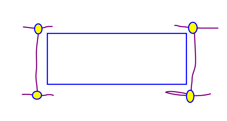
I've come to rationalize it like this, with reference to the sketch below: for same direction twist, and only same direction twist, the unconnected braces force the four points shown below to maintain their relationship to one another (the rectangle). The rectangle can sway and rotate, of course, but the relationship between the two beams is maintained. Hence their twin-ed-ness is preserved.

c01_pvyaaf.png
 
Status
Not open for further replies.

Part and Inventory Search

Sponsor