Continue to Site

Eng-Tips is the largest engineering community on the Internet

Intelligent Work Forums for Engineering Professionals

  • Congratulations waross on being selected by the Eng-Tips community for having the most helpful posts in the forums last week. Way to Go!

Brace frame bracing 4

Status
Not open for further replies.

Venkat Ashrith

Structural
Feb 8, 2022
5
I'm designing a brace frame and I have a question regarding fixity. (Geometry file attached)

Its a chevron bracing system. It has grvaity loading and inplane loading. I want to ask if we can assume that the column is braced by the brace at the location where the brace connects to the column. Lets say the column is 40' tall and the brace connects to the column at a height of 10'. Can I take my unbraced length to be 30'?

Usually point braces differ from where the column is loaded. Here the braces loads the column, so I was wondering if it can be considered that the brace, braces the column.

 
Replies continue below

Recommended for you

You forgot to attach the file.
 
It's dependent on the strength and stiffness of the brace. If you search for papers by an engineer named Yura you'll find a lot of valuable information on the topic. Your profile says you're in the US, so if you have AISC 360 handy I recommend you open up Appendix 6 and the commentary for A6. Especially the commentary.

And le99 is right. File's not there.
 
Until you say otherwise, I'll assume that we're restricting our discussion to column buckling coincident with the plane of the frame

Venkat said:
What is not sitting with me right is that the element this is loading the column is also bracing it.

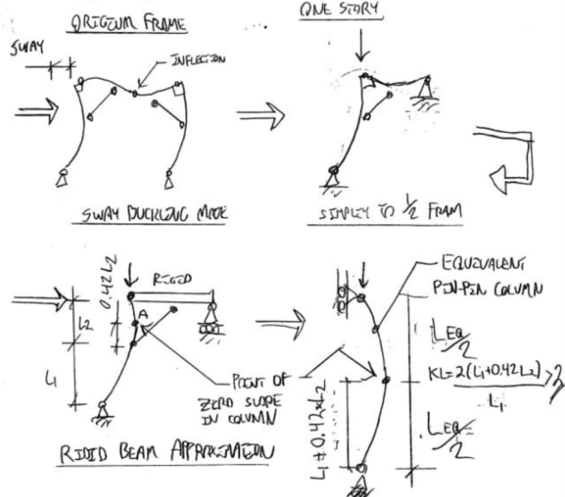
I don't believe that the braces do restrain the columns against sway buckling. It's sort of a semantic thing though. The knee braces will shorten the effective lengths of the columns a bit relative to an ordinary moment frame and do, thus, kind of "brace" the columns in that sense. The braces will not subdivide the columns into two, K=1 columns meeting at the brace tie in location.

The sketch below shows an estimate of your effective length for the column, non-conservatively assuming that your beam is rigid. To simplify things, a lot of engineers will just analytically replace the knee brace with a conventional beam-column rigid frame joint and design the columns on that basis (K > 2X story height). This will be conservative for the design of the columns but, usually, not excessively so.

c01_ce1mvs.png
 
Kootk, Only one correction, I dont have a knee brace per se since the brace connects to the column at lower than the mid-height (I agree that the markup attached is a little misleading). Your conservative analysis would work when its somewhat at the top of the column. How would your answer change if lets says the brace connected at 10' from the ground for a 40' tall column.
 
My answer wouldn't change at all Venkat. In my opinion, it's still a knee brace conceptually , even if the proportions are a little atypical
 
Kootk, I have a related question in a baroader sense. A stupid question.

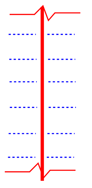
You say that unbraced length is from the points where the double derivate of the deformed shape changes and hence thats not at the point where the brace connection happens. Like we see in the picture attached, when we have bridging for a beam we take the unbraced length as the bridging spacing for LTB even though the deformed shape for the beam (uniformly loaded) is the a u shaped semi circular one. Why is that the case?

I know I am missing something

I know for Column we have to consider 3 limit states minor axis compression, major axis compression and LTB. And for beam usually its only LTB.

Screenshot_2022-02-09_100018_ib7aeg.png
 
I understand in the case of a beam, we are talking about LTB and hence the deflected shape doesnt matter. Similarly can't we assume its brace at the connection for flexure in the inplane direction?
 
OP said:
You say that unbraced length is from the points where the double derivate of the deformed shape changes and hence thats not at the point where the brace connection happens.

I didn't say that actually, at least not quite. In the context of the two problems that you've tabled here, I would say that the effective lengths are roughly twice the distances between points of maximum slope and points of zero slope. That, because you're trying to draw a parallel between your physical situation and an equivalent, pin ended column. If you apply this concept to both of your situations, you should arrive at consistent result.
 
Venkat Ashrith said:
Like we see in the picture attached, when we have bridging for a beam we take the unbraced length as the bridging spacing for LTB even though the deformed shape for the beam (uniformly loaded) is the a u shaped semi circular one. Why is that the case?
You are confusing the deformed shape under load due to elastic elongation with the buckled shape. The deformed of a braced beam that undergoes LTB is not 'semi circular'.
 
If you do not need the space beyond the elevation of the braces, and the beam-column connection is rigid, change the brace to a horizontal tie may change the inflection point in the column.
 
Status
Not open for further replies.

Part and Inventory Search

Sponsor