Continue to Site

Eng-Tips is the largest engineering community on the Internet

Intelligent Work Forums for Engineering Professionals

  • Congratulations waross on being selected by the Eng-Tips community for having the most helpful posts in the forums last week. Way to Go!

ANCHOR BOLT DESIGN FOR AN ANGLE BRACKET ATTACHED TO CONCRETE WALL (OUT OF PLANE LOADING) 4

Status
Not open for further replies.

kaffy

Mechanical
Jun 2, 2020
188
Good Morning fellow engineers,

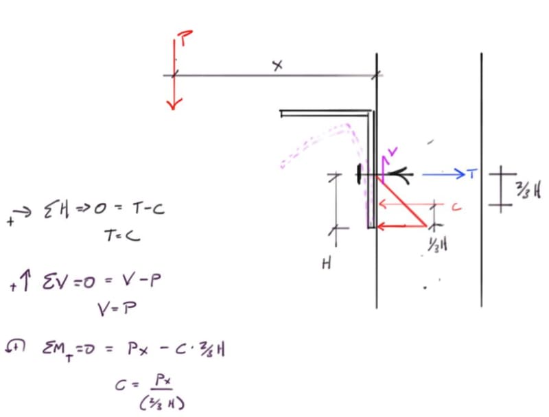
I am working on angle bracket design which will be attached to concrete wall with expansion anchor bolts (as shown in attached PDF).
Here is what I am planning to do.
As there is a eccentric out of plane load acting on bracket, it is going to try to pivot about the bottom edge
(I understand if we have more than one rows, then we take the neutral axis at the centre of bolt group case 2).

Based on the assumption it is pivoting about the bottom edge (please correct me if my assumption is wrong)
I will get the shear force and tensile force on anchor bolt as shown in calculations.
Now all I need to do is design my acnhors based on that

(Concept remains same whether it was anchor or any other bolt, Only difference is in anchor bolt, I will have to check anchor pullout, base material splitting, base material failure etc as well)


Am I missing something?

We do not use hilti so I can not use profis and the dewalt software do not let u put load at eccentric position

Thank You very much
kaffy


Replies continue below

Recommended for you

Capture_w8ijhs.jpg


I'm making a thing: (It's no Kootware and it will probably break but it's alive!)
 
Just because you don't use Hilti, etc. You can run the calcs using HAS E-55 epoxied inserts and substitute ASTM F1554 Grade 55S1... else, you can develop a spreadsheet that does it.

Am I the only guy that does't use a triangular load distribution? I've used a rectangular load distro, like limit states concrete design for 50 years... Unless you have a flexible attachment, the steel is likely much stiffer than the concrete.

Rather than think climate change and the corona virus as science, think of it as the wrath of God. Feel any better?

-Dik
 
I should add that my sketch is very general in your case the load twists the angle bracket prior to getting resistance from the bolts so the Moment should include the addition of the torsional component from the angle bracket span between anchor locations. You've also go the angle oriented in what I call a weak orientation, as you are relying on the more flexible leg to develop the compression bearing component rather than the stiffer heel, such that the triangular pressure I have drawn will likely be more of a tear drop shape reducing the moment arm between the tension and compression forces.

I'm making a thing: (It's no Kootware and it will probably break but it's alive!)
 
@celt83, So u took the pivot point at center of hole. Also the compressive load generated is at 2/3h. Is there any code reference stating that this should be taken at 2/3h? Or is it because the load distribution is triangular so the centroid?

Also please correct me if I am wrong. Every time the pivot is at center (if single row then center of hole, if more than one rows then center of bolt group. Also after selecting the pivot, load distribution is triangular both above(tensile) and below(compressive) the pivot point)

Thank you very much
 
@Dik, so If u use a rectangular load distribution, compressive load generated is at h/2. Everything else stay same. Is that right?
 
If at all possible, I'd recommend flipping the angle such that vertical leg points upwards (EDIT: Celt has now mentioned this). This will tend to concentrate the compression reaction behind the horizontal angle leg and creates a much more favorable situation with respect to prying. I acknowledge that there are sometimes detailing concerns that make this arrangement impractical.

dik said:
Am I the only guy that does't use a triangular load distribution?

No, lots of folks do this. I used to do it myself long ago. These days, I mostly use Celt's proposal. That said, even Celt's model may be unconservative with respect to prying action for certain combinations of angle leg and wall thickness. (EDIT: Celt has now mentioned this with the "teardrop" business)

dik said:
I've used a rectangular load distro, like limit states concrete design for 50 years...

I see two problems with that:

1) It doesn't account for prying action on the bolt.

2) It assumes that there is a ductile, yielding, tensile steel element involved (the rebar in ULS concrete). Most anchors will not yield in a ductile fashion prior to a developing a brittle, concrete breakout failure frustum.

dik said:
. Unless you have a flexible attachment, the steel is likely much stiffer than the concrete.

Steel is a stiffer material than concrete. That said, an 8" concrete member will often be stiffer than a 3/8" steel angle leg.

 
Nope... starting from the end of the angle... like a 'real' compression block.

Rather than think climate change and the corona virus as science, think of it as the wrath of God. Feel any better?

-Dik
 
Yup Koot... as I noted, except for fairly flexible connections.

Rather than think climate change and the corona virus as science, think of it as the wrath of God. Feel any better?

-Dik
 

My SMath program accounts for prying action, and often get a 30% increase in anchor force.

and, anchor loading is independent of ductile anchorage.

with a triangular stress distribution your anchorage force may be marginally greater and your prying forces would be similarly increased.


Rather than think climate change and the corona virus as science, think of it as the wrath of God. Feel any better?

-Dik
 
dik said:
...and, anchor loading is independent of ductile anchorage.

I disagree because:

1) Your anchor loading is a function of your assumed distribution of concrete compression stress.

2) Your assumed distribution of concrete compression stress is a function of whether or not you have ductile anchorage.
 
dik said:
Yup Koot... as I noted, except for fairly flexible connections.

And OP's situation, in the absence of a vertical stiffener or jello like concrete, will be flexible.
 
So Summing up

The reason we take the load acting at h/3 is because the load acts in triangular fashion and the centroid is at h/3.

The reason other orientation is preferred because at the generated compressive reaction load, we have another leg to stiffen it up.

In case I had more than 2 bolts, lets say 4 bolts then the calculation will be as followed(as shown in attached pdf) based on following explanation ( .

The Case II method assumes that the neutral axis passes through the center of the bolt group and simplistically assumes that all the bolts above the neutral axis have equal tensile stress and all the bolts below the neutral axis have equal compressive stress. The result is that you can use moment equilibrium to say that the couple created by the bolts equals the moment of the eccentrically applied force. The equilibrium equation is then solved for the bolt forces. This method is more direct and more conservative than the Case I method.


Thank You

 
Get a copy of Blodgette’s book: Link

The method to determine the bolt forces is in the base plate chapter. The link you posted assumes the bolts take the compression which is not the case here, the compression is taken by bearing of the angle leg against the concrete.

I'm making a thing: (It's no Kootware and it will probably break but it's alive!)
 
kaffy said:
The reason we take the load acting at h/3 is because the load acts in triangular fashion and the centroid is at h/3.

I would say that we do that because:

1) The rectangular, ULS stress block assumption is pretty unconservative and we hope to improve upon that.

2) We would like to know where the instantaneous center of rotation is but do not.

3) One thing that we do know is that the instantaneous center of rotation can be no higher than the anchor. So we put it at the anchor.

kaffy said:
The reason other orientation is preferred because at the generated compressive reaction load, we have another leg to stiffen it up.

No. We use the preferred orientation because it results in all of the vertical leg between the anchor and the angle heel pulling away from the wall. This allows us to make a realistic estimate of where the center of compression is located and mitigates most of the prying concern.

I agree with Celt that you're barking up the wrong tree with methods that were developed for conventional, all steel connections.
 
@thank you very much for valuable replies.
So during the different loading scenarios under different group of anchor bolts, we will have neutral axis placed differently and finding the location of neutral axis is what makes it complicated as we need more than one iteration and solve the equations.
I was checking the hilti profis and with either ledger angle or stand off condition (free version), I can simulate my loading condition (eccentric load in x, y, z) and determine the tension / shear force acting on bolt.
Dewalt also has free software where u can use the standoff and cross check the numbers.
As it is iterative, which design software do u guys use in case of complicated bolt pattern?
Also I understand that hilti basic and dewault assume rigid base plate for analysis. How do u check if the base plate is rigid??
 
Status
Not open for further replies.

Part and Inventory Search

Sponsor