Continue to Site

Eng-Tips is the largest engineering community on the Internet

Intelligent Work Forums for Engineering Professionals

  • Congratulations GregLocock on being selected by the Eng-Tips community for having the most helpful posts in the forums last week. Way to Go!

Light Gauge Steel-Stud and Track connection 2

Status
Not open for further replies.

Juhiimi

Structural
Mar 12, 2022
16
Hi everyone!

In advance, I want to say sorry for my English, especially for the technical expressions, they can be inaccurate sometimes.

Would you consider Bearing Resistance of the plate in a connection like the one below when we design the connection for axial load in the stud(Stud and Track of a light gauge steel residential structure) or we consider that the web of the stud and the track are connecting, and the axial load is transferred at the whole surface, not only at the fasteners? If I consider that the whole axial load is taken by the fasteners, then pretty much the bearing resistance is the leading design criteria, and I have to double the fasteners or the studs in many cases.

Thank you!
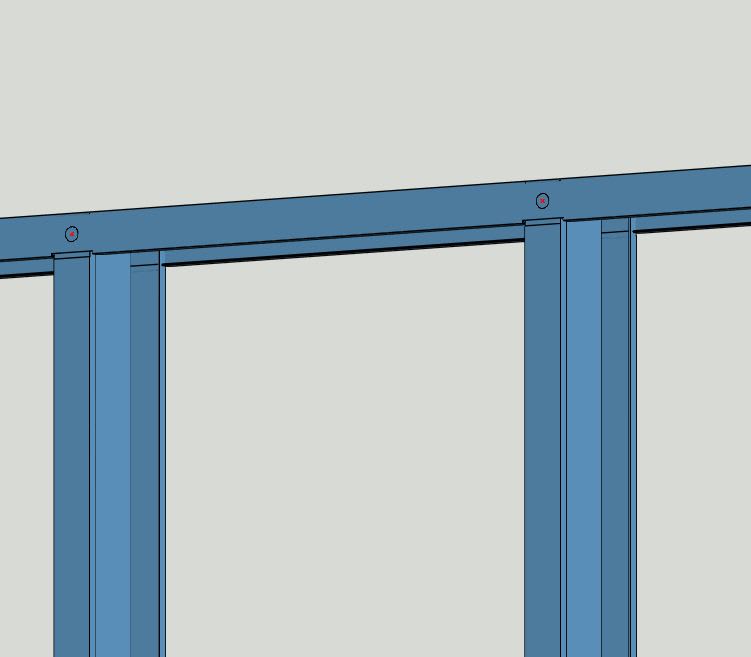
StudToTrack_ykwx99.jpg
 
Replies continue below

Recommended for you

Usually, the load is considered to be taken by direct bearing of the track web on the end of the stud.
Some bending of the track web probably has to occur before this happens - especially with heavier gage track- which has larger radius corners. Also, if the studs are not cut perfectly square, bending has to occur.
I think in reality, the load is taken up by both the screws and direct bearing.
 
Thank you!

So how could I make a more precise calculation, to not be limited with the bearing resistance at the fasteners? Or should I just consider the shear resistance of the fasteners?
 
I would not consider the fasteners at all - except for any uplift you may have.
 
1) I agree with XR250's assessment on this.

2) When last I looked into this, there was a prescribed limit on the allowable gap between stud web and track web. 1/8" or 1/16" I think.

3) This is, frankly, something that I've worried about too. If the fasteners would see the load first, then they'll just shear off is if some, other, ductile failure doesn't occur prior to that.

4) In reality, I think that these two things help your situation:

a) Fastener plowing should be pretty ductile, even if it introduces some slop into your uplift mechanism.

b) When the plate elements tend to slide past one another, the fasteners rotate in a way that probably allows some slip before serious fastener resistance kicks in.

5) Practically, there's just no way to make a go of these setups if the fasteners have to take all of the bearing loads.
 
Thank you very much KootK for the detailed explanation.

"b) When the plate elements tend to slide past one another, the fasteners rotate in a way that probably allows some slip before serious fastener resistance kicks in."

Can you elaborate a little on this affirmation, it's not exactly clear for me how to imagine this?​
 
Juhiimi said:
Can you elaborate a little on this affirmation, it's not exactly clear for me how to imagine this?

See the sketch below.

@rowingengineer: thanks for the video, that's a great contribution.

c01_ybknp9.png
 
Wow, thanks for the video @rowingengineer and also for the sketch @KootK everything is clear now :)

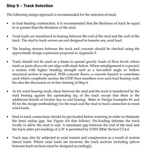
Also I found this:
Capture_mp3fii.jpg


This means the connection should be preloaded to get the axial loads transferred directly between the track web and stud. How could they do that in the factory when they pre-assemble a single wall pannel?
 
Good question. I haven't done load-bearing steel stud on any of my projects. We've talked about it in office as a couple people have and they indicated theirs were all shop fabricated and erected on site.
 
I have seen them placed on a floor and blocked in place.
Then small hydraulic jacks are used to deliver preload.
There is a heavy beam at top and bottom to keep things straight.


= = = = = = = = = = = = = = = = = = = =
P.E. Metallurgy, consulting work welcomed
 
Did LGF design for 20 years. Never saw pre-compression done in the field with stick framing.
 
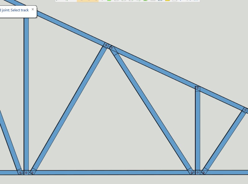
How about a truss made out of LGS? I think here we have to consider that the axial load is taken entirely by the fasteners, do you agree?

Capture_ehxran.jpg
 
Yes, however these are mostly axial loads the the web's don't see as much. Here you design the fixings to take the load, maybe add straps or similar if you need too.
 
Nobody builds trusses like that. The members are oriented strong axis with the screws taking all the shear.
 
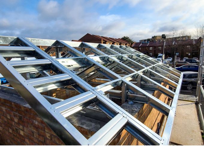
Agreed with XR250. Actually with his good advice a few months ago I designed / built a few different types of CFS trusses for various stairwell enclosure configurations. Screws transfer forces in shear as he noted.

Here's one of the roofs to give you an idea:

Cold_Formed_crja3o.jpg
 
The firm, where I started just this year, does this "in plane" trusses, like in the drawing I linked. We only do out of plane trusses if the openning is too big.

Which is the disadvantage of these kind of trusses, except of the smaller moment of inertia?
 
Status
Not open for further replies.

Part and Inventory Search

Sponsor