Continue to Site

Eng-Tips is the largest engineering community on the Internet

Intelligent Work Forums for Engineering Professionals

  • Congratulations waross on being selected by the Eng-Tips community for having the most helpful posts in the forums last week. Way to Go!

Cladded flanges 3

Status
Not open for further replies.

ElCidCampeador

Mechanical
May 14, 2015
268
IT
Hi,

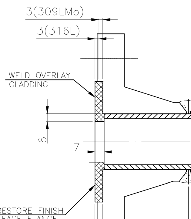
in an archive I've found a drawing of pressure vessel, design acc. to ASME VIII Div.1, where flanges are cladded as in the sketch here attached:
Flange_cladded_l5ohni.png


Flanges adopted were standard acc. to B16.5, mat. carbon steel, but raised face is completely removed (and also material from the inside body of the flange is removed) so that cladded layers are deposited on the surface to reach final dimension acc. to B16.5 and at the same time let cladding be enough for corrosion protection.

I know that in mechanical calculation, usually when there is cladding, this doesn't influence minimum thickness which is determined by carbon steel material.

But in this case, where part of carbon steel is removed from the body of flange and replaced by stainless steel? Is it necessary particular calculation, even if flange is standard?

Thank you
 
Replies continue below

Recommended for you

In your situation, you won't qualify for any thickness credit because you have removed the flange material to keep same length through hub per Div 1 rule UCL-23(b). The max allowable stress value will be the same as the CS base material.

But wait a minute. What is that big mismatch between the flange face and flange ID claddings? Can't you flush?

GDD
Canada
 
Flange in the picture with weld overlay has exactly B16.5 dimension. The only difference is that not all material is carbon steel but there is a weld overlay which substitutes part of base material (in particular internal bore and raised face plus something deeper).

From a stress/force point of view, I suppose that the part of flange most interested by stress is the thickness of the flange where there are bolts (and where cladding is not present). Could this be an "acceptable" explanation for skipping any kind of verification for flange cladded as in picture? Or does it depend how much deeper you choose to deposit weld overlay?
 
I don't think they have machined off any material from the flange bore? The drawing shows that it's perfectly matching the nozzle neck bore with cladding. The nozzle neck must have been cladded without removing any base material. Can you check on it? and what is the bore cladding thickness?

GDD
Canada
 
I'm with SnTMan.  May not be perfectly kosher, but it's very often done without calculations to justify.  I'm sure I've got hundreds and hundreds of flanges like this in vessels I'm the responsible engineer for.

If you'd like a little more "engineered" answer: Given the typically large gap between the B16.5 allowable pressure and the actual vessel/piping design pressure the allowable stress reduction on a very small volume of the raised face material shouldn't reduce the theoretical strength enough to "fail" the flange.

If you insist on doing a calculation be aware that many B16.5 flanges will not meet Div 1 App 2 rules as-is, so it may be impossible for this detail to pass.
 
I agree with my colleagues. the industry widely applies it without going to detailed engineering.

GDD
Canada
 
Ignoring the B16.5 issues and considering only the Code and welding metallurgy of the corrosion-resistant overlay, some thoughts:

1) The weld overlay was qualified to a certain minimum deposit thickness (T). Removal of overlay to a thickness less than T puts the flange in violation.

2) Is weld overlay considered to contribute to flange strength? Often designers will not take credit for weld overlay.

3) In my experience, using conventional welding processes (SMAW, SAW, GTAW, GMAW, FCAW) three (3) layers are necessary to achieve essentially full chemistry in a 316L overlay. Some will argue that it is possible using weaving and well controlled automated process mode (and they are correct), but I have witnessed 2-layer 316L back cladding rotting outside in weather. The problem is that the critical alloy element Molybdenum is expensive, and I have never seen an MTR for either base or weld metal with Mo higher than 2.25% (specified range 2 to 3%). With Mo that low you just cannot achieve >2% Mo in the second layer. Also, 309MoL is a must for the first layer; many folks start with 309L.

Remember, Section IX says nothing about the suitability of a qualified CRA overlay for corrosion service. I caution you against leaving a marginally resistant overlay on a flange face where crevices are found.

A pedantic point (not really): 'cladded' compared to 'clad' is redundant. I surmise from your handle that English is not your first language, but many English speakers make the same error. (Just one of the many exceptions English is burdened with.) Considering that 'clad' has meanings other than weld overlay, the word is best avoided altogether (it is used in Section IX, but it has no official defined status). There are two variants of weld overlay in Section IX:

QW-214 Corrosion-Resistant (Weld Metal) Overlay
QW-216 Hard-Facing (Weld Metal) Overlay

"Everyone is entitled to their own opinions, but they are not entitled to their own facts."
 
Clear, well stated and very informative, ironic ... Thank You !!!

It seems to me that, based on the abundance of this design, there should be some specific rules in the codes and standards about these !!

MJCronin
Sr. Process Engineer
 
MJCronin,

It would be too difficult to implement, but I would like to see Section IX overlay qualification based on the number of layers instead of a dimension.

Another issue that has complicated my life in the past is designers leaving only 1/8" vertical space for back cladding. With conventional processes and practices there is almost no possibility of achieving full corrosion resistance once it is ground flush with the surrounding metal, which was the case with polymer reactor shells corroding outside in the yard.

"Everyone is entitled to their own opinions, but they are not entitled to their own facts."
 
IR, this is why many company specs require the surface chem after machining to meet specific Cr and Mo minimums.
I have seen this most often with higher alloy overlay.
And yes this usually leads to a three pass system.
And when selecting weld overlay remember that it will never reach the corrosion resistance of the wrought alloy.
If your piping needs to be built of 316, then 316 overlay is the wrong choice.

= = = = = = = = = = = = = = = = = = = =
P.E. Metallurgy, consulting work welcomed
 
Agree with your last comment EdS.
'Matching' is not the simplistic concept civilians think it is.
Likewise for 'weldability'.
Much depends on context and the intended application.

"Everyone is entitled to their own opinions, but they are not entitled to their own facts."
 
Status
Not open for further replies.

Part and Inventory Search

Sponsor

Top