Continue to Site

Eng-Tips is the largest engineering community on the Internet

Intelligent Work Forums for Engineering Professionals

  • Congratulations KootK on being selected by the Eng-Tips community for having the most helpful posts in the forums last week. Way to Go!

Steel Beam Repair While Loaded 2

Status
Not open for further replies.

tacorns

Structural
Mar 22, 2022
1
Hello,

I have a 22' long W33x130 girder with corrosion issues. The top flange has become so thin that we now have to cut out the top 4" of the girder and weld it back in 2'-0" sections. The part that I'm struggling with is that this beam will still have a good amount of load on it when we cut it. We are able to remove the concrete slab + equipment on 1 side of the the girder, but not the other. Attached is my plan for making this repair. You can see that when we make the cut, the W33 essentially turns into a very tall upside down WT member (which does not check). To combat this, I plan to weld in 3/4" plates to prior to essentially turn it back into a shorter W member.

1) If possible, please provide comment on the plan itself.
2) I have designed the 3/16" Fillet for shear flow, but I am not sure if there is anything else that I need to consider. It just seems like a weak connection to me.

Thank you!


 https://files.engineering.com/getfile.aspx?folder=7897cbb7-93c8-4ff3-bc3a-e9ce3ebb8823&file=Document3.pdf
Replies continue below

Recommended for you

Welding to steel while loaded can be an issue. Have you taken into account a portion of the cross section weakened/not effective due to heating from the weld? That could be a issue. Also, your deflection will increase during this process.
 
If it's corroded that badly, not likely a really good idea. You, likely, need to provide a temporary support, or sister the existing beam. Any remedial work will likely be too hot for that sized beam.

Rather than think climate change and the corona virus as science, think of it as the wrath of God. Feel any better?

-Dik
 
tacorns said:
We are able to remove the concrete slab + equipment on 1 side of the the girder, but not the other.
These statements don't add up
tacorns said:
the W33 essentially turns into a very tall upside down WT member
Assume the concrete slab is bearing on the girder flange, if you remove the flange entirely then your remove the support for the slab coming in from both sides no?

Agree with WARose and Dik regarding the other items they note.

I'm making a thing: (It's no Kootware and it will probably break but it's alive!)
 
OP said:
1) If possible, please provide comment on the plan itself.

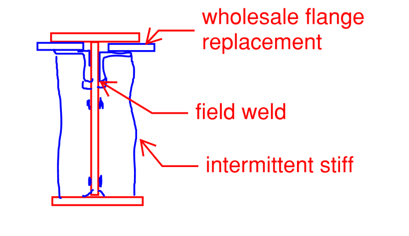
Without beating around the bush, you plan sounds very difficult, expensive, and prone to weird stress redistribution issues. I've pitched an alternative below if this could be accomplished without interrupting nearby services etc. It seems to me that, if you're going to bother welding temporary flanges on, you might as well just go ahead and weld permanent flange replacements on and dispense with the 2' cut & replace business.

OP said:
2) I have designed the 3/16" Fillet for shear flow, but I am not sure if there is anything else that I need to consider. It just seems like a weak connection to me.

If you go with your original plan, I wouldn't mind seeing some intermittent, partial height stiffeners below the new / temp flanges for an added measure of rotational stability.

Are you fairly confident that this is not a composite beam?

C01_mb54xr.png
 
Hi
I think you need to make a thorough analysis based on some rather interesting problems.

In the top left figure you start by welding two plates. Those plates will initially not carry any load, simply because the original beam supports the load.
The you cut the W33 and now the plates will support load and have stresses, you cut away a load supporting part of the cross section. But the stresses in the new "beam" will probably be higher since the beams height is lower. On other hand, as I understand it, you reduce the load so the stresses are not necessarily higher.
Then you add the new T-shaped top and again it won't support any load initially. And so on.

Now I have skipped the possible effects due to the welding. But I think you need to consider the effects due to that the supporting cross section changes. And that can be a challenge.

Thomas
 
I do a lot of this type of work in mineral processing plants.

First of all it's hard to give any good advice without knowing the surrounding conditions. For example bracing under the W33, floor beams framing to the W33, horizontal bracing, etc.

Making some assumptions the first thing I would look at is coming under the W33 with a new W33 then weld stiffeners or 1/2 round pipes to the existing W33 to make a series of posts to support the floor above. Actually first choice would be replacement.

Second choice weld a WT to the bottom flange and create a new composite beam (new WT plus reasonable assumption on the remaining W33) and add stiffener posts as described above. You could also fit in a new flange on the good section of W33 web like you are showing.

On the W33 new flange; I usually go stich weld in these cases. You have 22'*4 of 3/16" fillet, that is a lot of weld and shrinkage could be a problem.

Lastly, no matter what you do you have to consider residual stress in the existing W33. I suggest calculating a true dead load on the existing beam, estimate the section modulus of the good part of the the existing W33 (error to the smaller side). Now you can find the stress in the existing beam. Existing stress minus allowable is your allowable for the fully loaded composite section.
 
I'll see if I can find them; I may have left them at my old employers. I wrote a couple of spreadsheets to determine the strenght of S Beams with parts missing and also with a uniform thickness of material removed several years back... I used them for the floodway here.

Rather than think climate change and the corona virus as science, think of it as the wrath of God. Feel any better?

-Dik
 
I had intentions of replying to this thread and suggesting something similar to what KootK has proposed. I stopped by to give him a star instead. On that note, I see KootK is very near topping out the MVP list for the structural forum. Congrats and well deserved.
 
CANPRO said:
I had intentions of replying to this thread and suggesting something similar to what KootK has proposed. I stopped by to give him a star instead. On that note, I see KootK is very near topping out the MVP list for the structural forum. Congrats and well deserved.

Ditto!

Rod Smith, P.E., The artist formerly known as HotRod10
 
Thanks gentlemen. I was hoping that my detail would get a little more love. The one weakness that I'd considered is that, if the original top flange is too deteriorated to be the connection between the beam and the floor slabs, something new would have to be arranged. Without knowing more about the existing condition, it's hard to say what form that might take.

 
Status
Not open for further replies.

Part and Inventory Search

Sponsor