Continue to Site

Eng-Tips is the largest engineering community on the Internet

Intelligent Work Forums for Engineering Professionals

  • Congratulations KootK on being selected by the Eng-Tips community for having the most helpful posts in the forums last week. Way to Go!

Inclined beam analysis and model-STAAD 4

Status
Not open for further replies.

BulbTheBuilder

Structural
Aug 18, 2021
306
I am designing this inclined mechanical equipment on supports. I did my analysis by hand and inputted the loads manually in a STAAD model. Attached it a simple illustration to show my reactions (loads) on the supports. As you can see, there are shears introduced into the supports.
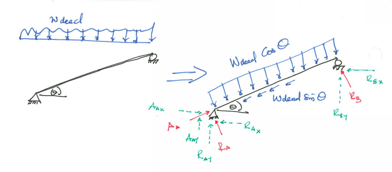
Screenshot_2022-04-05_081302_lbz4li.png

However, there's this discussion that there shouldn't be any shear in the support.

A simple model was done in STAAD pro and there was no shear in the supports but I am highly confident in my analysis and think there's something wrong in the STAAD sample model (sample model done in my office to prove their point; not Bentley default models). My only problem is, I can't figure out what is wrong. My issue is, if they decide to model it and there's no shear then the model is wrong (in my opinion). How do you model such scenarios in STAAD pro? Personal, I want to go with using my computed reactions as my loads rather than putting loads on the inclined plane.

Can anyone shed some light on how they went by such situations? I want to view things from as many perspective as I can.

[Edit] - I have attached a sample STAAD model
 
Replies continue below

Recommended for you

I do not know how to see your sketch/STAAD info. How do I do that?
 
Dead load should act vertically along the true length of the member not the horizontal projection.
You have a roller shown at point B therefore there cannot be an Rbx at this location.
Edit: see later reply on the horizontal reaction

I'm making a thing: (It's no Kootware and it will probably break but it's alive!)
 
@nevsam12 (Structural) I only have a sketch attached. I think you should be able to see it

@Celt83(Structural) Thanks for pointing at the "Rbx" in the roller. There's only Rby, I initial thought of making that support pinned for the illustration but changed it to roller to make it determinate and it simplified.

Celt83 said:
There should be a horizontal reaction at A with inclined framing
That's how I did my analysis but from a sample STAAD model was there no horizontal reactions. What other ways do you analysis your incline planes or there's something wrong with sample STAAD model or I am wrong somewhere?
 
Inclining a beam only introduces an additional normal force (axial) component; it doesn´t negate shear. The STAAD model is wrong. Perhaps it does not recognize that loads on inclined planes cause an axial load component; might have something to do with the chosen analysis type.

Remember to input both the cosine and sine components of the force in your calculations. The computer program can apply loads to "true length, vertical direction" as Celt83 mentioned, but for hand calculations, both components of the dead load (and possibly other loads, such as wind or snow) need to be accounted for.
 
Thank you @centondollar, I have to review literature materials on STAAD to resolve the issue then.

For my hand calculation I accounted for wind and seismic (using cosine and sine). Currently, there's an agreement that lateral forces will introduce axial component but the gravity loads is what I am trying to prove in STAAD. I am going to review "true length" feature or any other feature in STAAD and see how it goes. Thank you very much ladies and gents
 
sorry was operating prior to my morning caffeine dose.

For the dead load only case the load acts purely vertically and you have a rigid support at the peak, ie no thrust is generated, then there should only be vertical reactions. Internally the beam will have both shear and axial but the vector combination at the support will yield the vertical reaction.

For the wind/seismic cases you should get horizontal reactions.

if this is a raftered hip/gable then model both sides and remove the rigid peak support and this will show the thrust reactions.

I'm making a thing: (It's no Kootware and it will probably break but it's alive!)
 
You are absolutley correct! I want to hit my head against a wall....I was using internal forces rather. Thank you very much!!
 
BulbTheBuilder EI: I do not see your sketch. In fact I cannot see any Attachments from anybody. What am I doing wrong - or what am I supposed to do? Can someone give me directions? TIA
 
@nevsam12 (Structural) Do you have any security application that blocks pictures from loading? I don't know how to explain it but the sketch (picture) shows in the post. You might want to try different browser or different device and see if it works.
 
Thanks BulbTheBuilder EI for your advice. I will look into it.
 
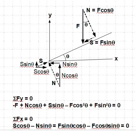
It can be explained by the engineering mechanics as shown below.

m_q3qdnv.png


Note: The stability of the beam can be maintained is based on the premise that the support is capable of developing the force, "S", required to stop the tendency of sliding. So in the connection design, the minimum required strength must be greater than the sliding force.
 
le99,

you are missing the right hand support reaction from your free body diagram. If the xy-plane is then placed so that the x-axis aligns with the inclined beam and the y-axis is perpendicular to the beam to simplify algebra, the y-reaction force balanace is:

SUM(Fy) = F*cos(theta) - N - Roller_support_reaction = 0 (N = the left (pin) support reaction)

and the x-axis force balance is

SUM(Fx) = S - F*sin(theta) = 0

What can be observed is a normal force in the beam equal in magnitude to the sine of the vertical loading, and a shear force.
 
@centondollar,

I purposely left out the "roller support" to simplify the demonstration calc. Even if it is included, it will only change the share of the normal force, but still has the full effect of the sliding force.
 
@nevsam12 (Structural) You're welcome.

@centondollar (Structural) & le99 (Civil/Environmental): I check my calculation realised the mistake I made was thinking the internal forces was going to exert shear just like @Celt83 (Structural) mentioned. Thank you all!
 
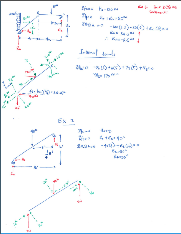
I did some sample calculation yesterday to affirm my faith. At the end of the day my hand calculation was correct but my STAAD model was wrong. Lesson learnt
Sample_i1rnww.png
 
Status
Not open for further replies.

Part and Inventory Search

Sponsor