Project Background
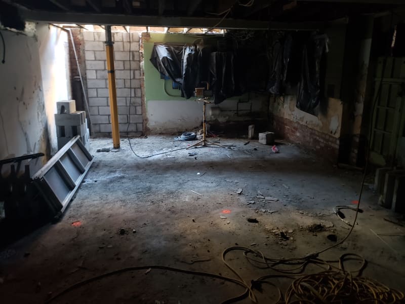
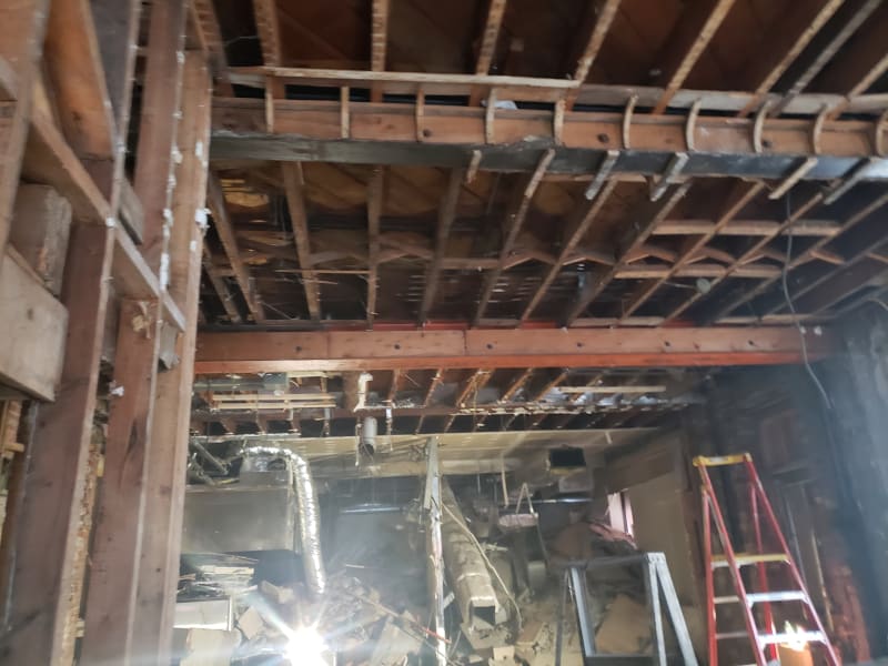
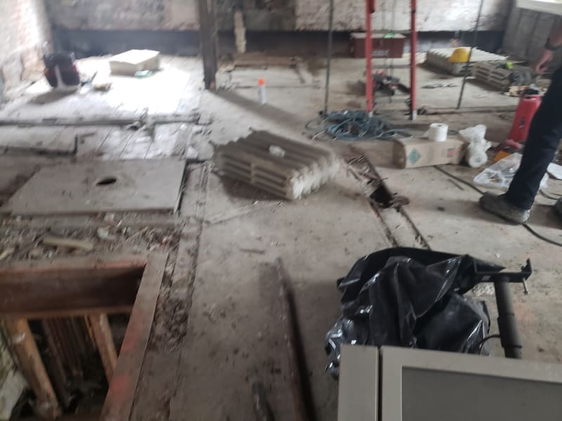
I'm shoring for concrete slab construction within the heritage component of a larger build. Existing interior floors are all suspended wood joists simply supported on W310 (W12) steel beams at 10-11ft centers. Façade stays but they are demoing a few of the existing suspended wood floors and replacing them with simply supported suspended concrete slabs (10” thick). The floor we’re starting on is the 3rd floor above grade so shoring must go through 2 existing wood floors to grade.
Retention of the façade and all that jazz is by others. I’m the designer for the formwork / falsework system only on this. Existing floor / joists need to stay but sub-floor can be mangled as necessary. Formwork system is Peri Skydeck with MP350 props. All very standard and good to go.
Unknowns
Existing layouts are all unconfirmed. The ceilings will be demo’d so we can get a good idea at that time. However, once that happens my client is supposed to be mobilized ready to go. SOG condition also unknown and will be site verified (depth / compaction of subgrade)
General Issues
I don’t know the best way to get the loads to grade. The joist layouts are similar(ish) between floors but can’t rely on them being identical which means typical towering and bracing schemes are not likely to work. Other issue is time is a massive factor. There’s a hefty, hefty time overage penalty on this for my client and so I need something they can go in with that will pretty much work no matter what they find (as mentioned it’s not open yet and they won’t know existing conditions until the day their clock starts).
Specific Engineering Issues
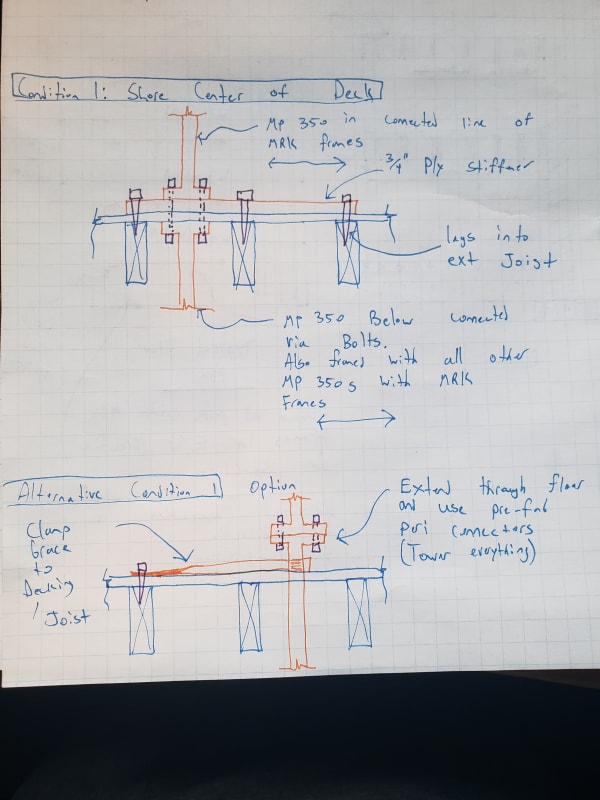
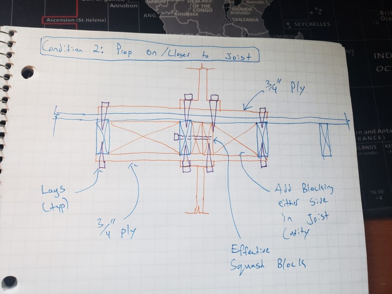
Curious about everyone’s thoughts on lateral stability where props line up on / near joists. Does anyone have a good feel for what kind of blocking might be reasonable to mitigate twisting / weak axis eccentricities / buckling at the point loads (see my sketch below). Short of blocking the entire cavity from one side to the other though I don't know of a warmy + fuzzy way to resolve that. Presently I'm thinking connecting all the MP 350 props in E/W direction (perpendicular to joists) and relying on the fact that the props/frames offer resistance against lateral displacement (through connection to my 3/4 ply plates / direct into joists with lags. There's obviously fastener slip concerns there but that probably wouldn't be large).
Also, movement when the load goes onto the old decking / joists. I need to check bearing/shear (maybe nominal bending for when props dont exactly line up) but any other significant issues anyone sees going onto the older stuff (any more likely to compress under high loads for instance)?
FYI my napkin math says load on each prop will be around 60kN (13.5 kips) with a 225 MRK layout.
Plan / Elevation Views
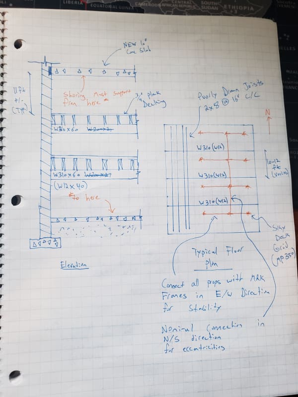
Condition 1 Options (Props line up between joists)
Condition 2 Option (Props are on or close to joists)
I'm shoring for concrete slab construction within the heritage component of a larger build. Existing interior floors are all suspended wood joists simply supported on W310 (W12) steel beams at 10-11ft centers. Façade stays but they are demoing a few of the existing suspended wood floors and replacing them with simply supported suspended concrete slabs (10” thick). The floor we’re starting on is the 3rd floor above grade so shoring must go through 2 existing wood floors to grade.
Retention of the façade and all that jazz is by others. I’m the designer for the formwork / falsework system only on this. Existing floor / joists need to stay but sub-floor can be mangled as necessary. Formwork system is Peri Skydeck with MP350 props. All very standard and good to go.
Unknowns
Existing layouts are all unconfirmed. The ceilings will be demo’d so we can get a good idea at that time. However, once that happens my client is supposed to be mobilized ready to go. SOG condition also unknown and will be site verified (depth / compaction of subgrade)
General Issues
I don’t know the best way to get the loads to grade. The joist layouts are similar(ish) between floors but can’t rely on them being identical which means typical towering and bracing schemes are not likely to work. Other issue is time is a massive factor. There’s a hefty, hefty time overage penalty on this for my client and so I need something they can go in with that will pretty much work no matter what they find (as mentioned it’s not open yet and they won’t know existing conditions until the day their clock starts).
Specific Engineering Issues
Curious about everyone’s thoughts on lateral stability where props line up on / near joists. Does anyone have a good feel for what kind of blocking might be reasonable to mitigate twisting / weak axis eccentricities / buckling at the point loads (see my sketch below). Short of blocking the entire cavity from one side to the other though I don't know of a warmy + fuzzy way to resolve that. Presently I'm thinking connecting all the MP 350 props in E/W direction (perpendicular to joists) and relying on the fact that the props/frames offer resistance against lateral displacement (through connection to my 3/4 ply plates / direct into joists with lags. There's obviously fastener slip concerns there but that probably wouldn't be large).
Also, movement when the load goes onto the old decking / joists. I need to check bearing/shear (maybe nominal bending for when props dont exactly line up) but any other significant issues anyone sees going onto the older stuff (any more likely to compress under high loads for instance)?
FYI my napkin math says load on each prop will be around 60kN (13.5 kips) with a 225 MRK layout.
Plan / Elevation Views

Condition 1 Options (Props line up between joists)

Condition 2 Option (Props are on or close to joists)


![[lol] [lol] [lol]](/data/assets/smilies/lol.gif) . But to his credit he's usually correct and I've also always considered him the better engineer of the two of us.
. But to his credit he's usually correct and I've also always considered him the better engineer of the two of us. 