Continue to Site

Eng-Tips is the largest engineering community on the Internet

Intelligent Work Forums for Engineering Professionals

  • Congratulations KootK on being selected by the Eng-Tips community for having the most helpful posts in the forums last week. Way to Go!

Irrigation pipe design

Status
Not open for further replies.

GrantBr

Agricultural
Jul 17, 2022
8
I’m having to relocate my irrigation system due to a state highway project and was needing some design input.

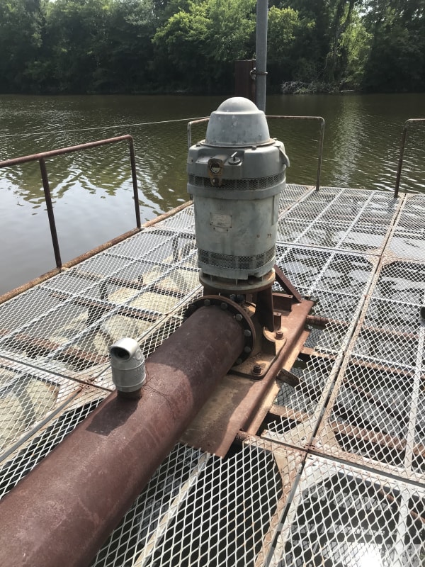
The current system consists of a 12” single stage vertical submerged turbine pump 5200gpm@40’head. It’s mounted on a barge and the pipeline consist of 500’ of 12” ips schedule 40 pvc with 5 45deg angles, one air break a few feet after the pump and another at the system high point (the top of the levee). The pump has a tdh of 45’ based on my simplified calculations. The pump discharge goes horizontal about 100’ then it has to rise about 25’ to go over a levee then it falls about 15’ into another horizontal run of a few hundred feet then discharges into an irrigation flume. One potential problem with the current system is the air break at the system high point (the top of the levee), it always has a vacuum there even when the pump is running normally and is continuously allowing air to enter the line. My thoughts are the air break should be automated and close when the pump is running or delete it altogether and install a check valve to prevent back flow. The other thing is, I think the piping should be larger and not as restrictive. One thing I would like to do in the future is eliminate the irrigation flume and replace it with an underground pipe, this pipeline will need to be about 1500’ in length.

I would like to get some input on how to construct the new system so it’s reliable and efficient.

Thank you
 
Replies continue below

Recommended for you

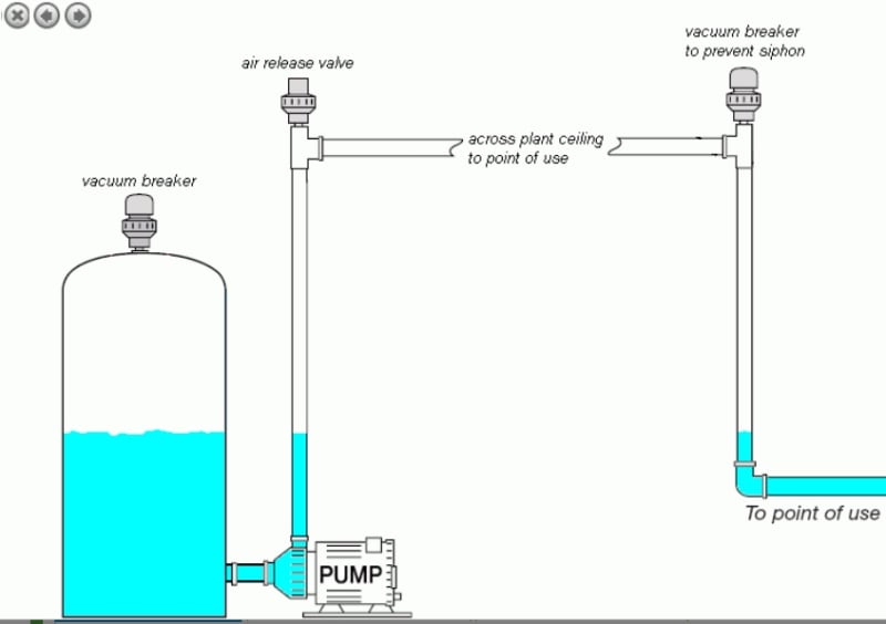
One potential problem with the current system is the air break at the system high point (the top of the levee)

Without a sketch reference, it seems that the water discharge needs a vacuum breaker in additional to the air relief valve, refer to the photo below.

Untitled_cliiij.jpg


To replace flume with the U/G pipe, you need to check the system to have a proper pipe sizing for the sufficient water hydraulic with the required pressure at the end service points. For a simplicity, the pipe route may follow the existing water levee if applicable.
 
Can you post the pump curve please. It seems s bit odd that your running a vacuum but you might just be running a slack line operation.

Remember - More details = better answers
Also: If you get a response it's polite to respond to it.
 
Washington State has many irrigation calculators online to assist in the design of these systems as well as guides to irrigation. Check the link:

Irrigation Calculators

 
Sorry for not replying sooner but where I’m working there is no cell service. I inherited this pump a couple years ago and all I could get from the pump manufacturer was the gpm and a installation/service book.

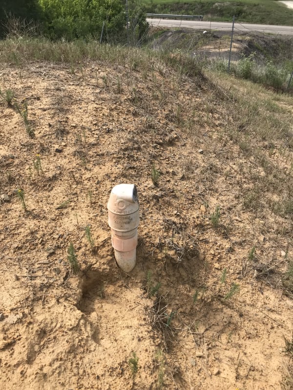
I may have used the term air break incorrectly, that’s what everyone around here calls them. This device is a simple floating ball in a cage. When there is no water the ball falls down and allows air to either enter or exit the pipe, if the water level gets high enough the ball will float to the top and seal the port blocking the water from flowing out. Like I mentioned before, the water never pushes the ball up and there is a vacuum there sucking in air all the time. At this time I’m not worried about the pipeline addition but making this one work correctly when I have to move it.

Basically I have a sump pump that has the discharge line rising 25’ above the pump and back down 10’ with an open ended discharge line with one air/vacuum break located 3’ after the pump and another located at the high point (25’)
 
GrantBr,

Air entrapment and column separation is common in long pipelines . It is a cause of surge/water hammer in many systems, if not designed correctly.
To work effectively, the following factors are of key importance:
1. Water discharge velocity (more important while filling in) - this will determine pushing of of air pockets and releasing in the air vents or entrapment of air pockets creating surge.
2. Location of air valves - usually at high points and change of elevation - air pockets are carried forward in flow direction in uphill but will back flow in downhill.
3. Function and Sizing of air valves - usually air valves are sized for different functions. One - for filling and draining the system and Second, for normal operation. Orifice sizes will differ in both cases. if air valves are not sized correctly, it becomes inefficient.
Usually, air valves are duplex - meaning they release air and intake air (vacuum break)

You can get good guidance for selection and installation of air valves in AWWA M51.

Not the least, air valves are the most neglected valves in terms of maintenance. Therefore, most likely, the valves will not be functioning as these are supposed to be.

GDD
Canada
 
Slack line operation is exactly how I’m opening. Given that I’m operating this way would it be better from an efficiency standpoint to create enough back pressure on the line to operate it as a tightline, or would this cause a reduction in flow and or decrease in system efficiency. Should the new line be designed to operate in the tightline mode.
 
Grant.

We really need a section view of your system starting at the water level as your base elevation as its not clear to me where all these things are. You say the levee is 25 feet high, but is this above water level or pump level or??

You have calculated 45 feet TDH - How?

I strongly suspect you are flowing at more than 5200 GPM or do you have an accurate flow measurement anywhere?

I would dispute what GD2 says that air entrapment and column separation are "common". They can occur when you don't design the system properly, but they should not be common.

This is to paraphrase it a pretty "agricultural" system and whilst I would normally say don't do it, in this case with such a low head application you don't want to mess with it too much. The key is how you operate. Does this pump go flat out for days or do you pump in batches? If batches then it might be more efficient to pump at a slightly slower rate and improve the pump efficiency, but first you need to know what your pump data is.

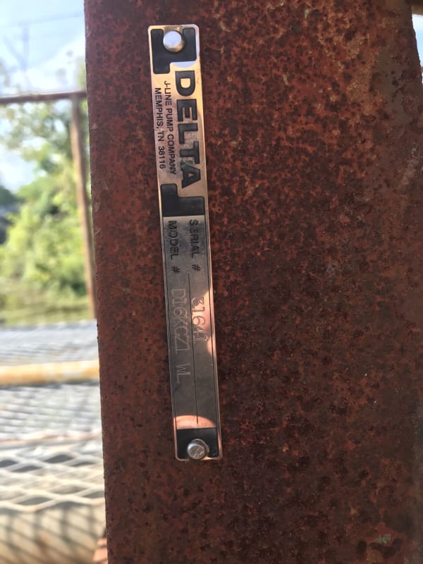
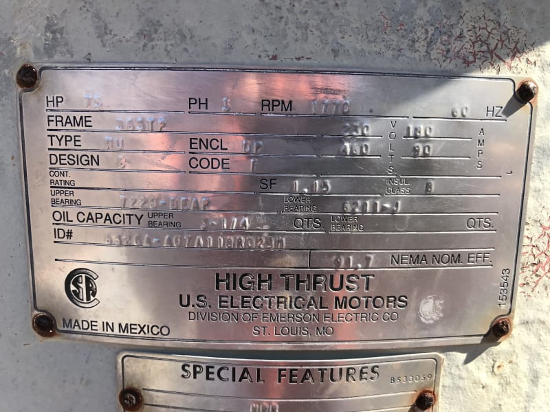
Can you post the pump make, model and any nameplate data? how is powered? If electric can you measure voltage and current going in?

As you new pipe is longer, the hydraulic gradient will be different and this may eliminate your issue with vacuum at the high point. But without the pump curve you can't calculate or predict anything. Do you have flow measurement at the pump? If you can then you could create a curve if you can't get one.

Remember - More details = better answers
Also: If you get a response it's polite to respond to it.
 
Thanks for all the help. I have requested the pump curve from the manufacturer again. I will take photos today and try an explain the system better. I have taken voltage and current readings before to make sure the motor wasn’t running unbalanced 472VAC and 84amps on each phase. The system is really rudimentary, I will try and get a pump discharge pressure next time I run the pump. The pump runs in batches, 12-14 hours on and 4-5 days off. I calculated TDH by adding the system static head and all the piping flow restrictions and friction using 5200gpm as the flow rate.

I’m not looking for a total system design but rather some thoughts on proper design and how it should be operated. Some do’s and dont’s and current system design failures, so I just don’t create the same problems again. I will be working with an irrigation company to make the relocation but there the same people that installed the current system about 10 years ago so I’m not totally conifident in them.
 
OK,

Normally you would want to run the system as a tightline operation that means your system downstream of the high point doesn't run the risk of unstable flow.
Your high point for this application needs the vacuum breaker to avoid it turning into a syphon when you turn the pump off. You could actuate the highpoint valve to close only when the pump is running which would also work, but you would need to be sure that the valve was open every time you stop.

At 5200 GPM you're doing about 4.5m/sec / 15ft/sec. That's on the high side of normal but for a short line won't make much difference. I can see where you're getting your additional friction losses (I get about 22ft for 500 ft). I think in reality though you're doing less than 5200 GPM. My guess is about 4000 to 4500 so that your head from the pump matches static head plus frictional losses. That's why a pump curve is needed.

So your longer pipe will either flow a lot slower with the same pump, probably about half the flow) or you need a new pump.

I haven't bothered to draw this out properly, but your current system must be nearly at atmospheric pressure at the high point so if you had a relatively small increase in head at the end (smaller section of pipe / orifice plate or a globe valve), you could achieve tight line flow with only a small amount of flow reduction.

But depends what you're looking to do - I've got a bit confused as to what this is now?

Remember - More details = better answers
Also: If you get a response it's polite to respond to it.
 
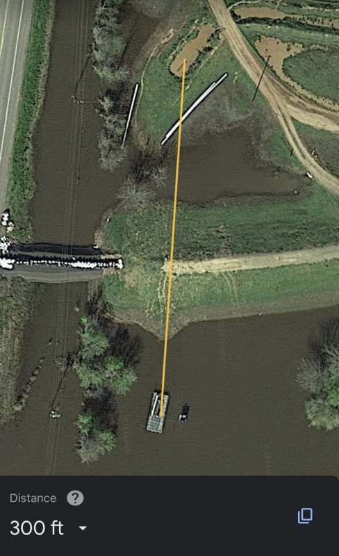
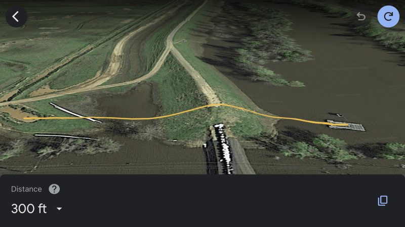
Here are a couple photos the aerial picture was taken during a flood a few years back but it shows the general layout. The other are nameplate photos. I will take a couple pictures today when I get up there.

56E529A6-D894-4446-8384-8EF1FF2F31AB_o894z5.jpg
A5D5A799-0A4B-4014-B028-B3AEF68AE847_bflqfk.jpg
6CB49AA6-44ED-4433-91B2-2B5938E311E8_muxgfo.jpg
8B885154-4997-4434-9579-5CC90FDB2BA3_gces2b.png
 
Well with a serial number I'm amazed they can't give you anything more than a supposed duty point.

J line seem to have turned into American Marsh (bought them out apparently),but none of their current ranges seem to match yours, though the Wilo turbine pumps come close.

and 300 ft of pipe is a lot different to 500 ft....

Remember - More details = better answers
Also: If you get a response it's polite to respond to it.
 
The barge usually sits about 30’ farther back and the 300’ shown on the drawing doesn’t account for vertical footage, it’s probably close to 450’ to be more exact.
 
What are the cons with operating a pipeline like this one in the slack line mode vs a tight line.


A713F5A5-1CD9-420A-98D3-A288344D7B1C_nblqoa.jpg
8E0914D2-2F31-4FA4-BDAE-177DC20A5AC0_ucqt8p.jpg
 
Al alternative to using a vacuum breaker, if the slack line pipe has no restrictions between the venting point and the outlet is to replace the vacuum breaker with a full size vertical pipe that extends to a point well above the highest grade line.

This arrangement hydraulically is the same as a pumping station lifting to a higher level and then the flow leaving the higher level is an open channel. To ensure no slugging, the slack line pipe should be about 1/2 full at the desired flow rate.
 
GrantBr,

To be honest, for what you are doing, there are few "cons" other than the water will tend to "gush", "glug" or "surge" out of the open end into your open channel with a fair amount of entrained air in it.

None of those things are that bad in an agricultural setting, but longer pipelines which enter into tanks or process equipment they are.

So long as the pipe and the end is secured so that it doesn't vibrate or move up and down and hence could fatigue itself out then you're probably good to go. you do though need that vacuum breaker otherwise you could easily continue syphoning water once the pump stops, either forward or more likely backwards. A check valve might prevent this, but an actuated valve would be better.

To get the same flowrate with your longer pipeline you will either need a bigger pipe (prob 16" or maybe 20") or a more powerful pump.

If you use the same size pipe and the same pump your flowrate will probably be about 2/3 of the current flow, but if all that means is that you pump for 18-20 hours then have 4 days off then you just use a bit more energy.

That's the balance you do when designing a system - bigger pipes = more CAPEX, but lower pump costs, lower energy required vs the opposite for a smaller line size.

At 1500ft, your economic flow velocity is going to be higher than it would be for longer lines, so you're probably at something like 3.5 m/sec.

Does that help?

Remember - More details = better answers
Also: If you get a response it's polite to respond to it.
 
Yes this all helps. Thanks for everyone’s feedback. The pump manufacturer did respond to my request for a pump curve, they said call my local distributor, the distributor said he doesn’t have it and he’ll try to get it from the manufacturer, we’ll I guess we’ll see. The distributor did say that according to the model number that that pump had been trimmed for either flow or horsepower requirements. Now that makes it that much harder to nail down. I’m pumping today and I’m going to take some velocity readings through a culvert and try to get some flow measurement.
 
Status
Not open for further replies.

Part and Inventory Search

Sponsor