Continue to Site

Eng-Tips is the largest engineering community on the Internet

Intelligent Work Forums for Engineering Professionals

  • Congratulations KootK on being selected by the Eng-Tips community for having the most helpful posts in the forums last week. Way to Go!

2 story shear walls 3

Status
Not open for further replies.

DoubleStud

Structural
Jul 6, 2022
458
The example on Bryer book has 2 floor level with 2 shear walls at each level (exterior wall stacked)with flexible diaphragm.

Let's say now you have 2 shear wall on the upper floor (2 exterior), but then once you go to the first floor you have 3 shear walls (2 at the end and 1 middle). My question is, the reaction forces on the 2 shear walls from the roof diaphragm, do they go straight to the shear walls directly below them? Or do they somehow get distributed to the diaphragm below and then redistributed to the 3 shear walls (middle shear wall takes the majority of the tributary width). Or does the shear wall in the middle only sees the wind load on the floor diaphragm? I hope I am making sense.

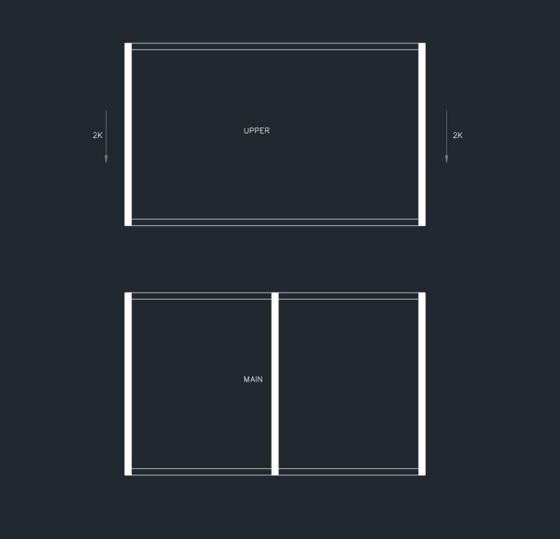
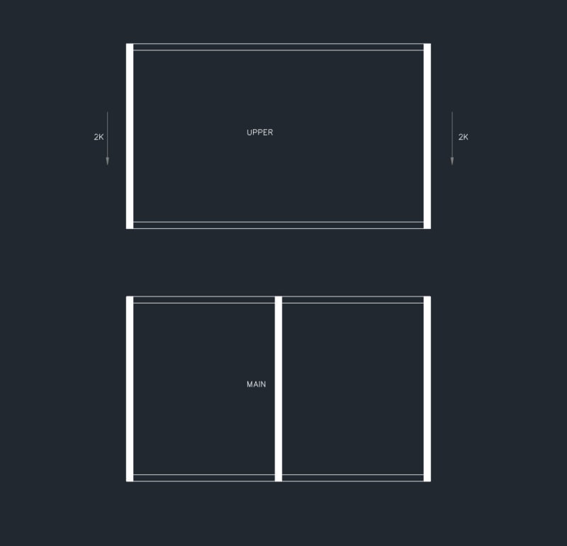
EDIT: Added sketch. This is the plan view. Do the 2K reactions from roof diaphragm go straight to the shear wall below them? Or some reactions will go to the middle shear wall as well?
2022-07-21_9-03-16_vyfd9r.jpg
 
Replies continue below

Recommended for you

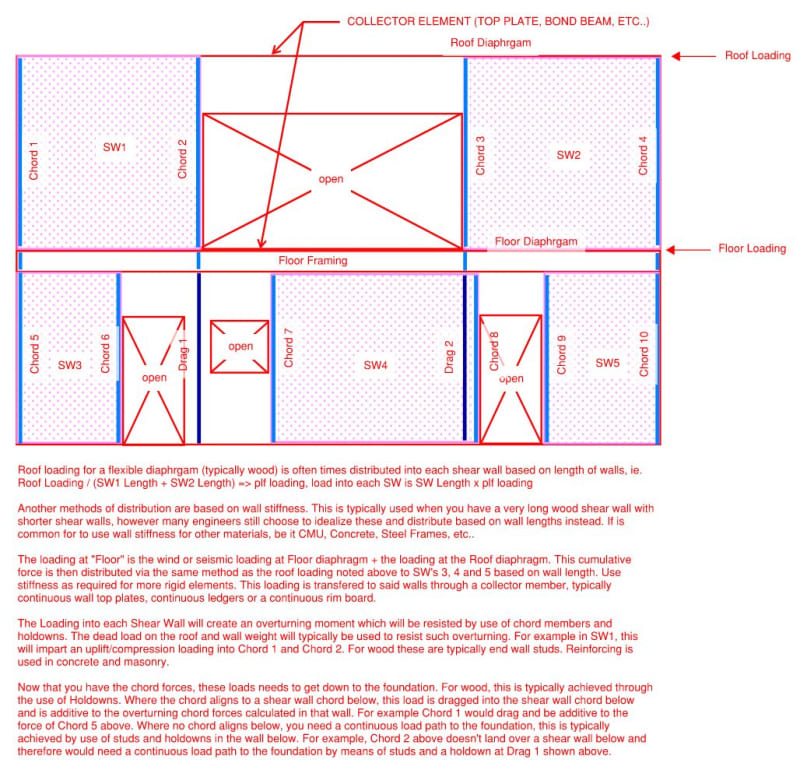
Please see the image below for a quick explanation of what I believe you are asking.
SW_Example_lfahlk.jpg
 
Question for you - how do you imagine shear walls 3 and 5 can deflect to resist the load, without shear wall 4 deflecting also?
 
No, you guys misunderstood me. Upper floor, west and east wall as shear walls. Then main floor west, middle and east wall.
 
DoubleStud, I think it might be best for you to post a picture of your situation. That way there are no misunderstandings.

I will take a stab at your question. As Tomfh is stating, you are missing continuity of the system. If you have 1 shear wall on the second level and 2 shear walls on the first level, and they are all connected with chords/collectors and diaphragms then load will be distributed to each of the two 1st floor shear walls in proportion to their stiffness (note: shear wall length could loosely be proportional to stiffness hence the comment in red above about distributing loads based upon shear wall length). This way, each shear wall will deflect exactly the same amount.... otherwise you don't have continuity.
 
Here is the plan view. Do the 2K reactions from the roof diaphragm go directly to the main floor 2 exterior walls? Or will it get redistributed to 3 shear walls?

2022-07-21_9-03-16_lkqlw9.jpg
 
Two concepts I believe you are asking about (SteelPE is right you should make a sketch if you want people to see the problem as you do).

1) The diaphragm is modeled in such a way that there is Uniform Shear at any location. That means you need a full length collector on the edge where the reaction is to take the load from the diaphragm. For wood frame construction this is often the rim joist, or can even be the double top plate.

2) NDS (SDPWS2015) 4.3.3.41 Says : "Shear distribution to individual shear walls in a shear wall line shall provide the same calculated deflection in each shear wall". NDS is saying that the whole line is going to deflect as one, and therefore the force in each wall is related to its relative stiffness in that line.

Review collector force diaphragm, shear wall deflection, and stiffness compatibility for deeper insight.

Essentially if you are to follow these provisions explicitly then you would need an iterative procedure. One that I use is to first assume that stiffness is proportional to length as Steel PE suggests. Then you size the shear panels, chords and hold downs. After this first iteration you can determine the stiffness of each wall panel in the line (using NDS deflection equations) then re-distribute the force but this time based on relative stiffness. Size the shear panels, chords and hold downs again until there is some convergence.

3) In general with a flexible diaphragm once a force is in a shearwall it is going to stay in that stack of shear walls as you go down the building. So no the 2k reactions on the perimeter walls of the upper floor will not be tributary to the interior wall on the lower level. The wall on the lower level is only responsible for its tributary at that level.
 
If I understand correctly, the top of the outer shear walls will carry the roof loads (gravity and diagram loads). At the second-floor level, the walls will carry the loads above and the second-floor loads (gravity and diagram loads). The load now is resisted by all three shear walls.
 
So Le99, are you saying the diaphragm load from the roof will go to the 2 shearwall, then go main floor diaphragm, then to the 3 shear walls?
 
Based on my (admittedly low) knowledge of flexible diaphragms, I would say that the shear in your upper walls will ALL transmit directly to the walls beneath them, and the interior wall spanning from ground to the 2nd floor will only see the shear from the diaphragm on top of it.

In order for that center wall to take shear from your roof, you'll need some level of rigidity out of the diaphragm on top of the main floor walls.

Long story short, I agree with driftLimiter's 3rd point:
driftLimiter (Structural) said:
3) In general with a flexible diaphragm once a force is in a shearwall it is going to stay in that stack of shear walls as you go down the building. So no the 2k reactions on the perimeter walls of the upper floor will not be tributary to the interior wall on the lower level. The wall on the lower level is only responsible for its tributary at that level.

Please note that is a "v" (as in Violin) not a "y".
 
Thank you winelandv. I believe you understood my question completely. Everyone agrees the middle shear wall will not see any load from the roof diaphragm?
 
Yes under the flexible diaphragm approach. Reality is of course muddy, if your lower level wall was especially flexible compared to the upper level and compared to the diaphragm, then it is possible that load would be shed from the outside towards the interior. However for a building like this the flexible diaphragm approach (100% flexible) is perfectly acceptable.
 
The roof diaphragm loads are taken by the end walls, then down to the foundation. The second-floor diagram distributes its load to all three walls. I am picturing you have 3 shear walls on the first floor, the middle wall is discontinued below the second-floor slab.
 
Status
Not open for further replies.

Part and Inventory Search

Sponsor