Continue to Site

Eng-Tips is the largest engineering community on the Internet

Intelligent Work Forums for Engineering Professionals

  • Congratulations KootK on being selected by the Eng-Tips community for having the most helpful posts in the forums last week. Way to Go!

Double Plate Shear Splice 1

Status
Not open for further replies.

driftLimiter

Structural
Aug 28, 2014
1,329
Does anyone have any references on designing double plate welded shear splices on steel WF girders?

Risa Connection checks the limit states handily, however it forces me to match the web thickness across the joint.
Makes sense from a construction standpoint, but man it is costing my connected girders dearly in weight.

The nature of this frame line is such that there is a chevron brace with BRBS controlling the design of a girder (W36x160).
Now I need double plates to drag the load into that sucker so the beam I am splicing it with has to match the same web thickness 0.65" makes for a heavy beam no matter which depth class I choose.

If I could shim out or deflect the splice plates Then I could perhaps get away with a smaller web and a much smaller beam on the drag side of the frame.

The drag beam that calc'ed out without consider this is a W24x76, in order to match web thickness the next least weight beam I could find is W24x146! A local reinforcement at the connection would certainly be more material efficient but I'm not finding any resource on that and I'm not even sure it could be built properly because the shims would need to be pretty tight tolerance and most likely off dimension thicknesses.

Your all collective wisdom and advice would be appreciated here. I suppose its not the end of the world if this collector line is twice the weight but it feels so wrong to put a beam with a UC less than 0.5 up there.

I suppose I could try to make all the splices work using one sided, but with the loads at the braced frame I really don't see anything fitting. Things are getting pretty close to UC 1 with a double sided GR 50 PL 5/8"x24"Dx32"W with 5/16 Fillet weld to beam web. It feels big. Don't really have a feel for whats going to be cheaper and easier, an (even more) monstrous splice plate and welding configuration or just heavier girders.
 
Replies continue below

Recommended for you

I'd shim the beams on both sides of the joint and make that make that generous to help with tolerances and to avoid dealing with stupid small shims. You can shim a fair bit before it starts to affect capacity and, even if it does affect capacity, the reductions are surely worth it to retain double shear splices and to avoid the adjacent beam oversizing which I do feel is egregiously wasteful.
 
So your saying ad web doublers to each beam so the built up web of both of them is the same size. But if I do this I would need to use nonstandard plate thickness on at least one side. Im starting to feel like just size up the girders there are only (4) of them in the entire building which is ~ 940'x420' so ultimately its not really alot of cost. It follows the KISS method which I like, something about adding custom thickness Gr 50 web doublers just seems wrong to me.

I also tried running through everything with single plate. My biggest plate is a Gr 50 1-1/2 x 24 x 63" with 3/8 fillet welds. To me this seems more erroneous then subbing a W24x146 for a W24x76, but again I don't have much a feel for it. Also not a fan of the additional eccentricity due to one sided plate.
 
driftLimiter said:
So your saying ad web doublers to each beam so the built up web of both of them is the same size.

Not doublers, just shims. You could do doubles but that would be more costly and I don't see the need for it.

driftLimiter said:
But if I do this I would need to use nonstandard plate thickness on at least one side.

If you provide a generous width within which to shim, as I suggested, then the fabricator should be able to devise a shim stack that gets you within 1/16" of where you need to be.

Is your connection transferring significant shear in addition to axial load?
 
Is this a roof? If so, could you run a strap over the column tops to connect the top flanges of the adjacent beams?
 
No very little shear compared to Axial load something like 1/10th of the axial load. So a local shim stack but wouldn't each layer of shim need to develop down to the layer below and eventually the web, I guess I am not able to picture the load path from the web to through the shims. I would need to have the same amount of weld from the splice plate on each shim down till I get to the web is what I am thinking. Yes it is a roof but the deck is running flush over the top of the collectors. I could explore a full moment splice of the beams but there just would be more components because the beam depths are unequal.
 
driftLimiter said:
would need to have the same amount of weld from the splice plate on each shim down till I get to the web is what I am thinking.

You seem to be harboring a misunderstanding of some kind about how shimming works. It's not necessary to weld shims together in most applications. They float loose.

driftLimiter said:
...a local shim stack but wouldn't each layer of shim need to develop down to the layer below and eventually the web

The shear enters the bolt at the splice plate and leaves the bolt at the girder web. The bolt rotates a small amount across the shims and creates a sort of strut and tie field within the shimmed space. The bolt supplies the tension for that STM and the shim stack provides the compression. It's a bit like how wood screws installed on the diagonal work to create composite members out of individual, stacked members in wood.

 
I've only ever studied the shimming thing in single shear applications, where it makes sense to me. For double shear, it starts to feel more like straight up bolt bending. You might want to look into that before running with it.
 
Any chance you'd be willing to share the design shear/axial load? Never used RISA Connection but if I was getting those results I'd be diving deep into the design assumptions the program is making. It may be the case that the eccentricity of the shear is controlling your design as the length of the plate increases.

Have you considered dragging the load through the flanges rather than the web? Since you're asking about a beam splice connection, it seems like this is a roof condition with the beam running over top of the column, correct?. Even at the roof, I'll typically extend the column up to the top of the beam and transfer the drag force through the column web or, if required, continuity plates in the columns. You can also try adding a loose plate over top of the beams to carry the drag force as KootK suggests.

Page 5.289 of the AISC Seismic Design Manual (3rd Ed.) includes a design example for a double shear splice for shear / axial. It's bolted rather than welded but I'm sure there's lots of useful info for you to glean.
 
What kind of shim thicknesses are you looking at? Per AISC 360 Section J5.2, anything less than 1/4" thick results in no bolt shear capacity reduction.

When you go above 1/4" thick, you can either take a bolt shear capacity reduction, OR you can weld the filler to the web. (there's a bolt option buried in J5.2(b) but I've never seen anyone use it).

Please note that is a "v" (as in Violin) not a "y".
 
drifLimiter, can you confirm that you are asking about a welded shear splice and not a bolted shear splice? Seems like that is causing some confusion.
 
I've been assuming an axial/shear splice bolted on both sides of the joint to girders that meet at some location away from a column.
 
Unless there's a large difference in web thickness... I generally ignore the difference and let the shear plate yield... clamping forces are still pretty high and I'm not concerned about anything backing off.

So strange to see the singularity approaching while the entire planet is rapidly turning into a hellscape. -John Coates

-Dik
 
Its a WELDED shear splice welded on both sides of the web. Vertical Shear 50 kip axial Drag load is 636 kip. I've poured over RisaConnection design checks and assumptions and Deker you're indeed correct the eccentricities introduced into the connection (particularly the offset in the beam CL due to different depth beams) causes a large bending moment in the plate that is typically driving the plate thickness quite a bit higher than the direct axial force.

And Deker your picturing it just right column to bottom of beam, beam sticks out beyond column with a propped tip, then the shear splice. I might try exploring some other configurations, I arrived on this one because it is the most direct and I think it involves the fewest components. Not to mention that at this particular intersection there is a lot going on, girders intersect the column perpendicular to the drag line which is why I opted to move this connection away from there. Doesn't mean we couldnt run the column up higher and have two perp. shear tabs plus this massive drag connection.


Since it seems like some of you are interested in the limit states I am sharing here the RISA report outputs (for the connecting elements) for two options at my worst case drag beam. I find Risa Connection to be the best RISA software that they offer because of the detail it shows in the calculations. You can see here the different limit states on the elements and the max UC for each.

The single plate option seems okay except for the fact that it is 5'3" long and 1-1/2" THK Gr 50. I really don't like the idea of that plate for some reason (maybe I'm mistaken).

As you will see in the double plate option the left beam is is quite a bit heavier, that is ONLY to accommodate the equal web thicknesses. Could I simply add a filler plate (shim) that is the same flush up to the outside of the splice plate then add more fillet weld to make up the difference? I believe you can do this for filler plates up to 1/4" Thk.
 
 https://files.engineering.com/getfile.aspx?folder=2e35a7b2-18bd-4952-a66e-6aa4180fce88&file=GL_G_options.pdf
Sorry, drift, I saw the comments about shims and my mind went off to a bolted connection. My apologies for not reading your problem more carefully.

driftLimiter said:
Could I simply add a filler plate (shim) that is the same flush up to the outside of the splice plate then add more fillet weld to make up the difference? I believe you can do this for filler plates up to 1/4" Thk.

When I read J5.1a, if you don't need the fillers to transfer the load, you don't make them transfer the load. What you do is:

AISC 360-15 J5.1a said:
...the filler shall be kept flush with the edge of the outside connected part, and the size of the weld shall be increased over the required size by an amount equal to the thickness of the filler.

So that's good from an engineering perspective, but the welder may not appreciate a 5/16" weld becoming a 9/16" weld (for a 1/4" plate) - something to keep in mind as you play around with different web thicknesses.

One thing that isn't clear from your print out, is where are you putting your zero moment point? Based on the calcs that it is giving, it appears that RISA is saying that the zero moment point is the weld centroid on the right (W36x160) beam - per the "Plate Flexural Yield Check" e[sub]x[/sub] is 23.16". I would contend that the zero moment point should be in the middle of the splice plates. That will reduce the moment demand by about 24 kip*ft on the plate (shear * e[sub]x[/sub]).

As for the vertical eccentricity, couldn't we say that the W36x160 is strong enough to be able to accept the moment from offset centerlines and keep that eccentricity out of the connection? In my mind, I'm envisioning a shear lag (yes, like from Part D) effect, but for compression. That might be totally off-base, and if it is I'm sure some of the more mechanically sound members can correct me.

At any rate, if you CAN reduce the moments on your connection, then you should able to (hopefully) reduce your weld size. If you can get it down to a 3/16" weld, than you can have a filler plate of 1/8" thick on each size and still have a single pass weld.

Please note that is a "v" (as in Violin) not a "y".
 
When I was going through the problem manually I also figured the point of no moment was at the centerline of the splice. It seems to me that eith this assumption the plates still need to carry the full moment, but aisc says if the connection is symmetric then the welds would designed for half of the moment. I liken this to a beam model with a clamped slider and a point load. I need to think about the mechanics of that eccentricity some more cause I agree that risa I think made a simplification that is turning out maybe too conservative.

Ex in this case is taken as the distance between the weld center of gravitys.

The vertical eccentricity statement about the flexural stiffness of the w36 need to think a out that this weekend while kayaking :)


AWS allows root openings up to 3/16" if the fillet weld size is increased by the amount of the roof opening. Probably counterproductive since I'm guessing your goal in sizing the fillet weld is to keep it single pass. You might consider switching to a bolted connection using 2 or 3 columns of bolts to make the plates more compact (able to transfer load throughout the depth of the plate rather than just welds on the edges). The bolts are more forgiving of gaps in the connection, and you can eliminate the bottom cope on one of your girders.

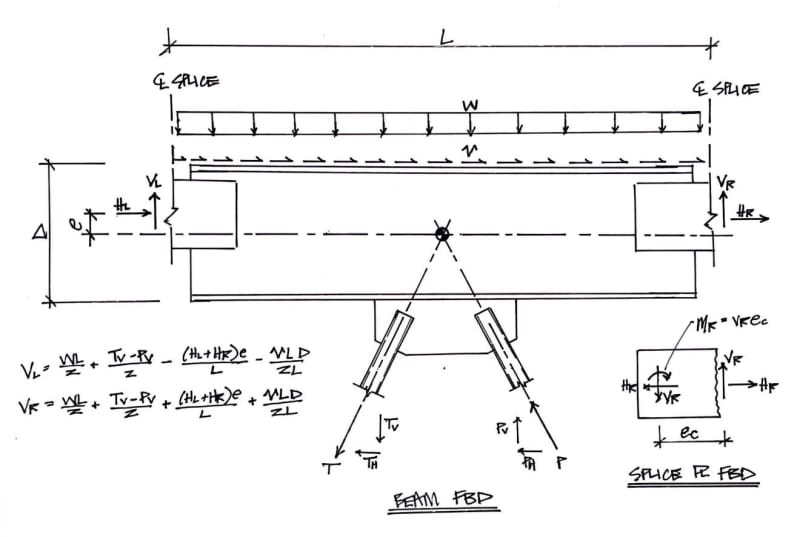
I agree that the point of zero moment would be at the centerline of the splice so long as that is consistent with how you designed the framing. I'd also be designing the connection for direct axial (no eccentricity) since the strong-axis stiffness of the W36x dwarfs the stiffness of the connection. Obviously be sure the check the beam for this additional moment.
 
Deker said:
I'd also be designing the connection for direct axial (no eccentricity) since the strong-axis stiffness of the W36x dwarfs the stiffness of the connection. Obviously be sure the check the beam for this additional moment

I want to get on board with this, I believe this is the approach taken in the past for this detail at my office. I'm am however having a hard time reconciling the statics of this assumption. I guess what were saying is that I order for moment to really enter the s pp lice plates, it has to have a compatible rotation with the end of the W36, if I did a stiff ess analysis of the joint there would be only a small rotation of the w36 that would only develop a small moment in the splice.
 
This is how I see the statics of your condition. Detail the splice plate to accommodate the beam end rotation like you would for an extended shear plate.


Scan_Aug_1_2022_wmpvll.jpg
 
Status
Not open for further replies.

Part and Inventory Search

Sponsor