Bridge_Man
Structural
- Apr 2, 2020
- 42
Hi,
I am reviewing a design that was performed using L-Pile for a shaft foundation to support a noise wall embedded post. Basically, the post will support the panels above grade, and the same post will be embedded in a Unreinforced shaft below grade to a certain embedment.
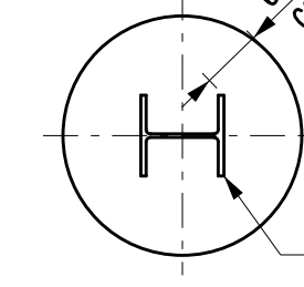
The section defined in LPile is a Round concrete Shaft with permanent casing and core, Casing was not defined, and no reinforcement were defined as well. only the insert (w-shape) and the concrete shaft were defined as allowed by LPile
Those posts do not have shear studs below grade, and as previously mentioned, the shaft does not have any reinforcement. This design is typically used for such walls. AASHTO requires minimum vertical rebars in the shaft to consider a composite action, and since the shaft is unreinforced and no studs are available I would think that the shaft will be considered plain, and will crack when it reaches the cracking moment, and then the steel shape will be engaged which will fail once it reaches the plastic limit (assuming its compact)
LPile however, considers the embedded pile and the shaft to create a composite behavior and considers that in the moment capacity calculation. where I think it should only be limited to the steel shape, so If I calculated the plastic moment capacity of the steel shape and compared it to what LPile is providing I will find that LPile's moment capacity is much higher than the steel shape (maybe 3 times higher or more)
I do understand that there is a possibility for a partial composite action to be found, but I don't think the code allows such a thing.
I thought of using the elastic section but Please remember that I actually need the actual concrete shaft to provide the geotechnical stability of the system, but I also need the embedded post to transfer forces and provide the structural resistance of the system and exceed the moment demand along the shaft length.
Can you provide an insight into that, any recommendations, am I looking at this wrong? how to make L-pile understand what I want it to do.
Thank you!

