Continue to Site

Eng-Tips is the largest engineering community on the Internet

Intelligent Work Forums for Engineering Professionals

  • Congratulations waross on being selected by the Eng-Tips community for having the most helpful posts in the forums last week. Way to Go!

Another ridge beam thread (with added purlins!)

Status
Not open for further replies.
Apr 25, 2017
279
GB
Hello,

Obviously the topic of ridge beams has been done to death here, but what I haven't seen much of is the role that purlins play.

I've been asked to take on the regular structural engineering for a traditional oak framing company (in the UK) and one of their comments was that the previous engineer ridge beams were always specified as massive - much larger than their competitors were installing.

(Edit - typical roof is a traditional cut roof with large king post or queen post trusses at ~4m centres, with 2xpurlins and a ridge, and rafters spanning from wall plate over purlins to the ridge)

I explained the issues with small deflections resulting in fairly large thrusts at the wall plate, but I may be able to reduce the size since in a traditional timber framing, the chunky wall plates should be able to resist some thrust and carry it back to the main truss ties. I think if I can keep the wall plate lateral deflections very low then I am happy with doing that.

Thinking on it later, I was pondering the role purlins must also play in preventing the wall plate seeing that thrust.

My conclusion was that if treating the rafter as a continuous beam the the ridge beam may only be seeing 0.6x of the load of a purlin (reaction for 1.25xWL for a central support of a continuous beam vs 2x 0.375xWL for the end support).

And if treated as two simply supported spans they should have a very similar amount of load place on them (for the purlin, half the rafter span and for the ridge, 2x top half of rafters).

Until they send over some work this is all a bit theoretical but does that sound like a reasonable starting point? The topic of traditional oak framing hasn't been well covered in the UK as far as I can tell, but I expect there is some spot on text book I need to get hold of.
 
Replies continue below

Recommended for you

Yep. I've done some "historic" structures here in the States (the quotes are for your benefit - historic here is still young to you guys in the UK) with similar roof framing. The most recent was a church built in the mid 1800s. Large trusses at about 16 feet on center with 4 purlins on each side of the ridge. The rafters were a combination of double and single span with all of the rafters meeting at the ridge double span and met a ridge board that was 1" thick.

So it's certainly feasible to design and detail these timber roof systems to get the load off of the ridge and into the purlins while also resolving thrust issues.
 
George said:
...the chunky wall plates should be able to resist some thrust and carry it back to the main truss ties...

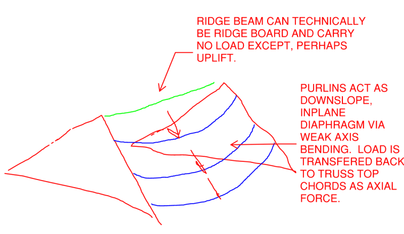
Meh. I might claim that load path in the context of a desperation play on an existing structure but I wouldn't normally consider that path to be desirable in the context of a new build without some very careful detailing to go along with it. Moreover, I don't think that you need to use the top plate that way. There's a much better story to be told about how the ridge beam is shielded from load. If I understand your situation correctly, the load path shown below will be much stiffer and stronger anyhow. And it ought not require unconventional detailing.

c02_ffistd.png
 
Thanks both.

A picture paints a 1000 words.

Usually there is only 1, at most 2 purlins, per side for the size of roof I am looking at.

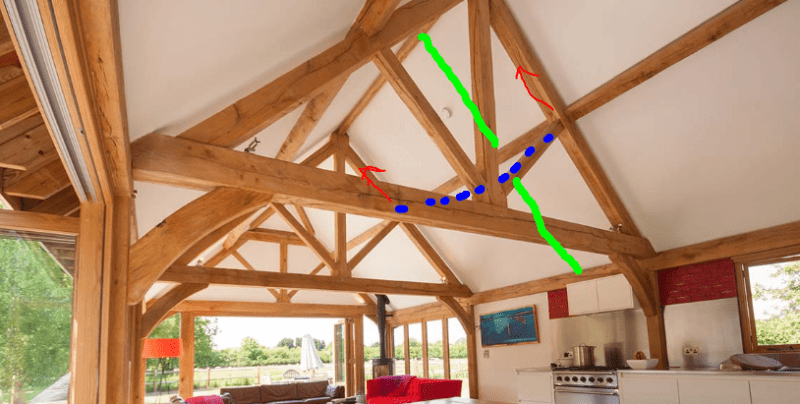
This would be a typical example (credit to Oak masters - not the company I was talking about tin the first post)

king_post_truss_roof_rl9azc.png


Yes I see what yo are saying. And the purlins are very often square sections laid in the plane of the roof pitch, so very effective at transferring thrusts back to the trusses.

In some cases on very short spans there are no purlins, in which case the wall/top plate may come back into play. But the forces are lower overall anyway. The detailing I'm not so worried about unless there was a splice involved.
 
Are you able to rely on the roof sheathing itself to provide the downslope diaphragm action? I know that this strategy is less popular outside North America.
 
Sheathing isn't common here (although interestingly, mandatory in Scotland). I did put a plywood sheathing on my own vaulted extension, which confused the roofers immensely.

It's also not something I've ever seen it in old timber framed barns and houses, so it shouldn't really be necessary.

Having a concept that uses the large purlins and wall plates is better.
 
George said:
Sheathing isn't common here (although interestingly, mandatory in Scotland)

Still, even if your "sheathing" is just decking boards, I'd be willing to bet they constitute the stiffest load path available in the plane of the roof.
 
In England the standard detail is tile battens straight onto the rafters. The breather membrane is attached straight to the rafters and drapes down to allow water to drain down to the eaves.

It's a bit different with a warm roof as there will be some sort of insulation board on top of the rafters but nothing necessarily structural.
 
Just to add to this, I was looking at my old barn with this type of roof.

I hadn't noticed before but there is a tie at midspan between the two purlins (behind the king post truss), this is presumably to prevent spread of the purlins with that lateral thrust.

This is onto a small wall plate sat on a masonry solid wall.

Note the ridge board (certainly not a ridge beam), so all thrust must being carried by the tied purlins.


King_post_tied_purlins_i1vzh9.jpg
 
George said:
this is presumably to prevent spread of the purlins with that lateral thrust.

Where I've practiced, this would not the case and that tie would be the difference between what is known as a "collar tie" and what is known as a "rafter tie". Collar ties are up higher than rafter ties and their purpose is to keep the rafters from pulling apart at the ridge under uplift conditions. A complete analysis of collar ties usually indicates that they are positioned too high on the rafters to supply the stiffness required to effectively resist their outward spread at the bearings.
 
As you can see in the picture, the tie isn't connected to the rafters, for that reason I wouldn't describe it as (edit - functioning as) a collar tie.
 
George said:
As you can see in the picture, the tie isn't connected to the rafters, for that reason I wouldn't describe it as a collar tie.

I disagree. The tie is connected to the rafters via the purlin as an intermediary. I stand by my original assessment.
 
Would the rafters need to be connected to the purlin for that roof system to work? I mean, of course they would be connected but if they were just bird mouthed and sat via gravity, without a ridge beam there would still be a a tendancy for the purlins to spread and the tie would resist that.

Obviously in terms of semantics it is a collar tie (I will edit previous post, should really say 'functioning as a collar tie'), but it isn't the same as a rafter collar tie roof in my opinion.
 
George said:
Would the rafters need to be connected to the purlin for that roof system to work?

Is that seriously a question? Of course the rafters would need to be connected to the purlins.

George said:
without a ridge beam there would still be a a tendancy for the purlins to spread and the tie would resist that.

The ties would indeed attempt to resist the spread of the rafters. However, due to the unfavorable leverage situation involed:

1) That load path likely doesn't possess enough stiffness for the ties to be effective in that role and;

2) In the unlikely event that load path was stiff enough for it to be effective, it would likely not possess enough strength to meet the required demand.

George said:
...but it isn't the same as a rafter collar tie roof in my opinion.

Then by all means, proceed assuming that your opinion is correct and that mine is wrong. My role here is to advise and recommend. The "deciding" is up to you.
 
I'm after understanding, please.

Yes - so clearly, as I said the rafters in reality be connected to the purlins. What I was trying to convey is more a thought experiment:

Imagine building a roof with no nails in the rafters, with everything slotted together via direct bearing with birdsmouths...

Ridge board - the roof would fail because the rafters would spread and it'd all fall apart.

Ridge beam - the rafters would stay where they are because there is no horizontal thrust.

Purlin roof as in my photo (with only a ridge board at the ridge) - the rafters would behave as they do in a ridge beam roof, because the purlins are performing a similar role to the ridge beam

Now, any sensible definition of a collar tie is that it connects two rafters together to prevent spread. In my picture it is connected only to the purlins and I think that any nails in the rafters are not actually preventing the spread, because the purlin is doing the role of the ridge beam ... and that is what is preventing the roof spread.

That is why I said I don't think it is functioning as a collar tie would normally. It is a semantic argument since that is what anyone would call it, but I cannot find any real definition of this 'purlin tie' in my textbooks and I want to fully understand its structural role.

Does that make sense? Like I say, i can't find any details investigation and in 'modern' king post truss roofs, the 'purlin tie' seems to be missed out. But I had a poke around 3 or 4 old barns yesterday and they all have one.

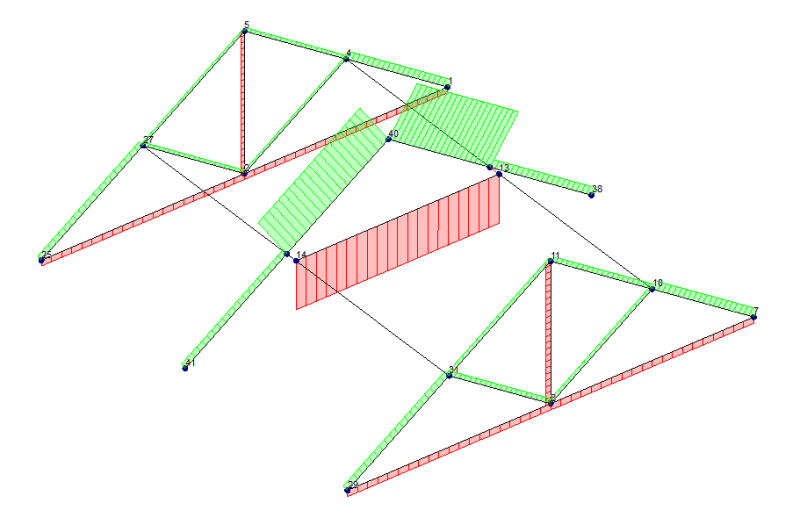
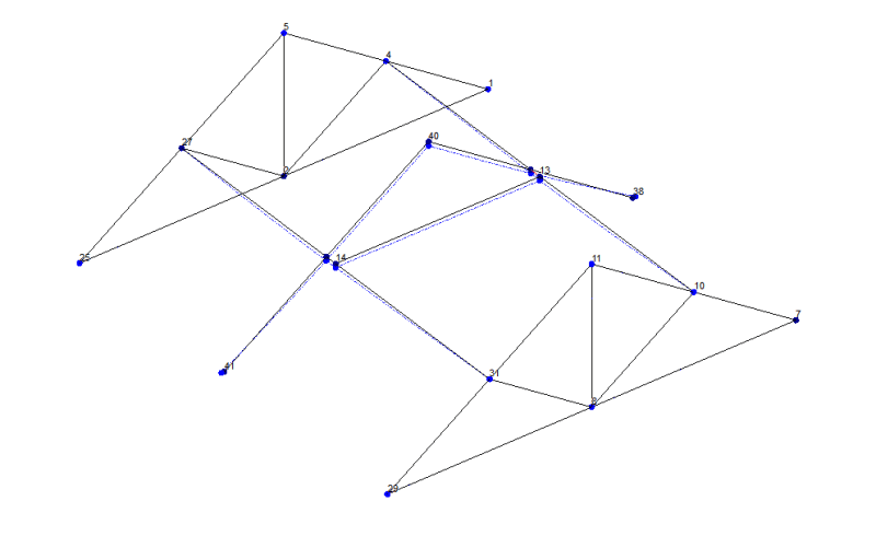
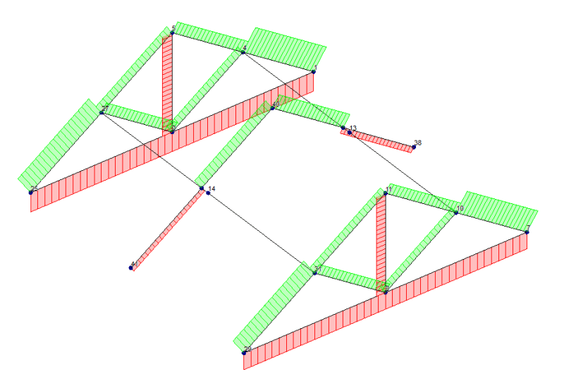
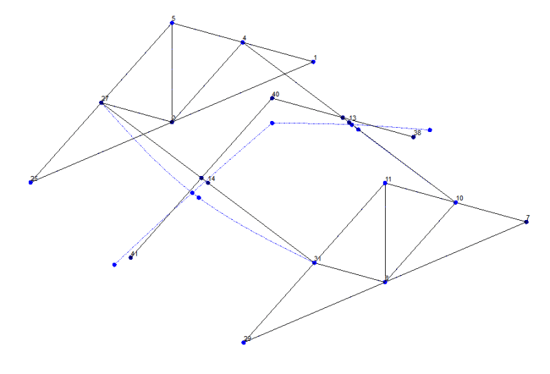
Edit - right, built a quick model. Very rough and ready:

ith the exact same loading (1kN at the ridge), roller supports on the rafters and highly exaggerated deflections and axial force (but the same for each model).

With the tie

Gets a tension force developed in the tie, as expected:
With_tie_-_axial_x10000_jy3e4q.png

With_tie_-_deflection_x100_uvnxdf.png


Without the tie:
With_no_tie_-_axial_x10000_dzprgy.png

With_no_tie_-_deflection_x100_dygi8s.png
 
Status
Not open for further replies.

Part and Inventory Search

Sponsor

Top