Continue to Site

Eng-Tips is the largest engineering community on the Internet

Intelligent Work Forums for Engineering Professionals

  • Congratulations waross on being selected by the Eng-Tips community for having the most helpful posts in the forums last week. Way to Go!

Design CMU bond beam for lateral earth pressure?

Status
Not open for further replies.

TroyD

Structural
Jan 28, 2011
98
US
I am assisting a residential architect with this proposed dwelling (see attached). The foundation wall is 14' tall, with full height backfill at the rear wall, tapering down along the sidewalls. Client is an experienced block layer, so I sized a heavily reinforced 12" CMU wall (using RetainPro) to resist the lateral earth pressures, and will call for granular backfill behind the wall. The lateral force at the top of wall is ~1,500 lb/ft (assuming granular mat'l). The location of the stairs along the rear wall going up to the dwelling is a conflict for utilizing diaphragm blocking in the first few floor joist spaces to distribute that load...I'm concerned about the best way to resist that lateral force.

Can the CMU bond beam at the top of foundation wall be designed with adequate horizontal reinforcing on inside face to resist the lateral load? I assume the process would be similar to designing a CMU lintel. I ran the calcs quickly and I would need (8) #8 rebar on the inside face. 2 course bond beam required.
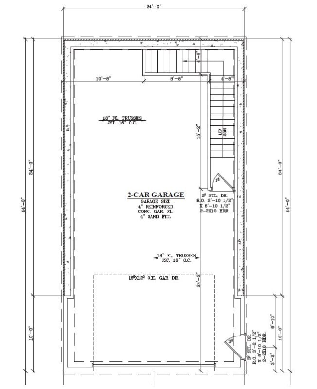
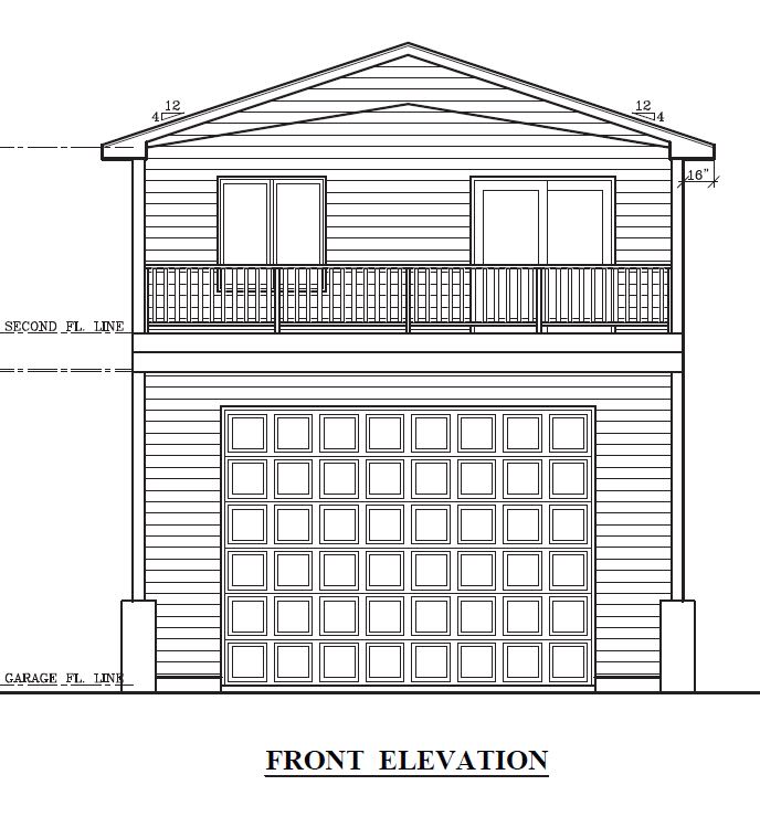
image02_mupfs5.jpg


image01_msy0fi.jpg
 
Replies continue below

Recommended for you

I doubt it and even if it could you likely could not get the load out of it and into the floor diaphragm. 14 feet of backfill is serious business and requires significant detailing to get it to work. I would look at trying to reduce your lateral pressure by backfilling with a different material. I don’t know how you would get that kind of load into the bottom for trust not have issues. You also may rack your entire foundation at the garage portal depending on which side the backfill is on.
 
I presume you are talking about the short span, correct?

It probably can be done, but if you are getting eight #8 bars in a 16” (wide) 12” deep CMU beam then I’d be looking for other issues which might be present.

Did you check shear? Shear is often an issue with CMU and you won’t have a way to add shear reinforcement. Deflection is probably worth worrying about as well. And anchorage to the diaphragm on the long sides needs careful consideration.

You might get better, more realistic results looking at it like a three-sided wall, free at the top and fixed at the bottom. If you want to consider it fixed at the sides you will have some careful detailing work to do.
 
JLNJ,

Yes, the short span at the rear of the dwelling. The client has also asked if this can be done as poured concrete walls. I will evaluate this as a rectangular concrete tank, like you describe...free at top, fixed at bottom. I have used the rectangular concrete tank manual for evaluating similar cantilever retaining walls on residential sport court foundations, etc. I will call for granular backfill, and evaluate with lateral earth pressures that reflect that...approx. 30 to 40 psf/ft. Will have to see what the wall design coefficients are for this wall width/height ratio in the manual.
 
Use the 12" reinforced CMU wall, but rather than figuring that the walls spans vertically, then horizontally at the top, why not span the wall horizontally all the way up? Or if you prefer your way, introduce a cast concrete beam at or near the top to span between the side walls. That beam would be covered in the backfill, so it can extend out horizontally from the building.

And yes, you can build the whole thing in reinforced concrete.

 
hokie,

Is there any benefit to adding a second heavily-reinforced CMU bond beam at a lower point on the wall? The stresses are greatest at ~6 ft height. But the wall vertical rebar will need to penetrate the bottom of the bond beam blocks, and likely interfere with the horizontal rebar in the bond beam.
 
Best to use H-Blocks, sometimes called open end blocks, and with the web cut down to allow for the horizontal bars. That allows for complete filling of the wall and as many horizontal bars as required, which is what you want.

 
You really either need to do some sort of tie-back system of figure a way to span that wall horizontally (24 ft is a long way). You will NEVER reliably get that kind of load into a trussed floor system via blocking. Maybe do an exterior slab similar to what Hokie said.
Even on the side walls, that is a shit load of load to dump into the bottom of trusses. You could potentially add 18" to your wall so the force goes directly into the floor diaphragm - even that is a stretch unless you can reduce your loading.


Good luck!!!!!
 
I also like to look at these walls as 3 sided. Not sure how much fixity you can achieve at the bottom unless you use a wider footing with reinforcement too. (see suggestion below)
Sidewalls near the back end will also have significant bending. Need to consider that too. Probably will have fixed edge behavior (unless you don't reinforce it horizontal and then you will have cracks at the corners so.... seems like horizontal bending will be a factor in the design. That should help with the side walls anyway (around the back corners at least).

One idea that should help the rear wall is to add a buttress in the middle. Looks like the stairs are running up along the back wall so you might be able to fit one in. You'll want a wide footing all the way across (I would think) to keep soil pressure lower.
 
Status
Not open for further replies.

Part and Inventory Search

Sponsor

Top