Continue to Site

Eng-Tips is the largest engineering community on the Internet

Intelligent Work Forums for Engineering Professionals

  • Congratulations waross on being selected by the Eng-Tips community for having the most helpful posts in the forums last week. Way to Go!

Circularity - measurement with caliper or micrometer

Status
Not open for further replies.

Andera

Mechanical
Jan 21, 2019
58
What would be the best explanation, in the layman terms if possible, on why circularity CANNOT be measured and qualified (per Y14.5’s definition) with a caliper or micrometer.
I was trying to convince and influence people that measuring the local sizes (taking consecutive measurements) and calculate their differences IS NOT circularity, but I failed to prevail on.

I am looking for more ammunition.

 
Replies continue below

Recommended for you

One reason why that method is invalid: A two point local size check will never be able to detect a tri-lobe form error.
 
Main reason I would use: There is no way to guarantee that all of the local sizes (spans across the circle at different rotations) will have the same center point, which is a core requirement of circularity.

John-Paul Belanger
Certified Sr. GD&T Professional
Geometric Learning Systems
 
If you have a hexagonal rod, measure each opposing edge and you get a size varying few hundreds of millimeter, does that make the hexagon a circle? By their logic it would mean it's circular, the size does not vary too much and you made 3 measurements.
It's just not how it works.
Also using a "wide" flat object to measure a 2D cross section is incomprehensible.
 
Give them a Reuleaux triangle to measure with calliper and mic, ah perfect circularity - or maybe not !
 
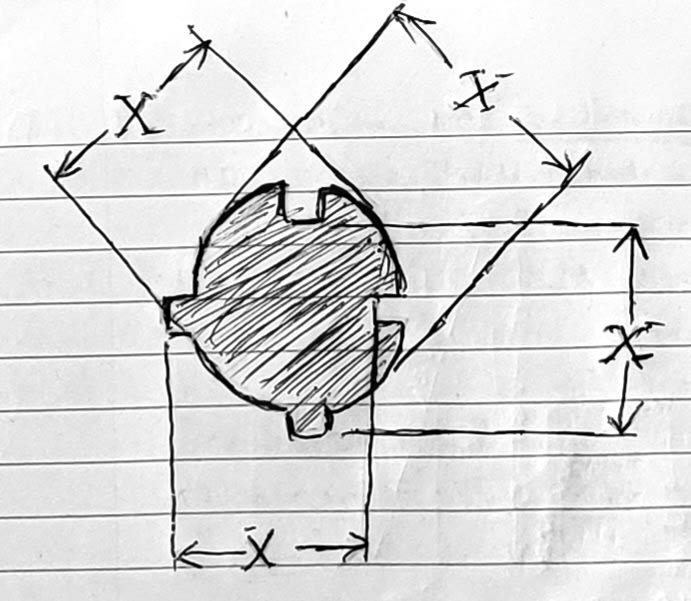
Draw them a prettier version of something like this. All actual local sizes (per the caliper/micrometer measurement) are identical, but the circularity is bad.

20220901_170758_l7oymz.jpg


Since they are measuring only the distances between opposed points, some configurations of circularity variation cannot be detected, however others can; it might provide some indication but not substitute the measurement.

Now, if they were measuring the difference between the maximum inscribed and the minimum circumscribed circles, that would be a different story. But then it would be over-restrictive. Maybe that's what confuses them. Tell them the difference.
 
Burunduk said:
Now, if they were measuring the difference between the maximum inscribed and the minimum circumscribed circles, that would be a different story. But then it would be over-restrictive. Maybe that's what confuses them. Tell them the difference.


Are you saying that if the parts are measured on the CMM (for example) and the minimum circumscribed and also maximum inscribed algorithms are used (instead of the default LSQ one) than the difference between those two values is the circularity error?
 
greenimi,
Not necessarily. The difference between Min circumscribed and Max inscribed may only indicate the maximum possible circularity error for a given cross-section, but it would be equal to it only at specific situations, such as for a cross-section of an otherwise very circular shaft that only has one unintended flat on it.
But if there is an approximately uniform, symmetrical form error similar to what a cross-section of a knurled shaft looks like, the maximum inscribed and the minimum circumscribed circles turn out roughly concentric, in which case the circularity measurement should provide the value of the radial distance between them, while the difference in diameters as measured would be twice as large. That's why I said "over-restrictive".

Does it make sense?
 
Attached shows why the MIC/MCC idea doesn't translate to circularity -- if you look carefully at the center point of each picture, they aren't the same. So Burunduk's idea only works if they are coaxial, as he mentioned.
All of the things mentioned above still boil down to the idea that circularity requires equidistance from the same common center point.

John-Paul Belanger
Certified Sr. GD&T Professional
Geometric Learning Systems
 
 https://files.engineering.com/getfile.aspx?folder=31b38e8b-ab8d-4acc-8e63-66bcdf3eeb20&file=MIC_MCC.png
Richard Feynman cited this as a problem in the space shuttle Challenger investigation. A shape can have uniform width all around but not be a circle.
 
Belanger,
You make another good point with your diagram, but my idea was different.

In your diagram the MIC and MCC are constrained to be concentric to each other, and you find the radial difference, showing the result differs depending on which circle "acts" first.

In my mind, the MIC and MCC are not constrained to each other, and the difference in diameter is being found. That difference represents the worst case circularity and only truly applies to a case such as a fair circle with a flat - it's sort of like why we shouldn't specify a circularity tolerance that exceeds the size tolerance when rule #1 applies. In the case of an error which is symmetric around the circle, the MIC and MCC are concentric and the difference in diameters is over-restrictive as a circularity evaluation, since the true value is about half of it. But as a worst case only evaluation, it should work.
 
From his book What Do You Care What Other People Think?

Feynman said:
Then I investigated something we were looking into as a possible contributing cause of the accident: when the booster rockets hit the ocean, they became out of round a little bit from the impact. At Kennedy they're taken apart and the sections... are packed with new propellant... During transport, the sections (which are hauled on their sides) get squashed a little bit - the softish propellant is very heavy. The total amount of squashing is only a fraction of an inch, but when you put the rocket sections back together, a small gap is enough to let hot gases through: the O-rings are only a quarter of an inch thick, and compressed only two-hundredths of an inch!

A more complete report:
 
Burunduk said:
In your diagram the MIC and MCC are constrained to be concentric to each other, and you find the radial difference, showing the result differs depending on which circle "acts" first.

In my mind, the MIC and MCC are not constrained to each other, and the difference in diameter is being found. That difference represents the worst case circularity and only truly applies to a case such as a fair circle with a flat - it's sort of like why we shouldn't specify a circularity tolerance that exceeds the size tolerance when rule #1 applies. In the case of an error which is symmetric around the circle, the MIC and MCC are concentric and the difference in diameters is over-restrictive as a circularity evaluation, since the true value is about half of it. But as a worst case only evaluation, it should work.


Burunduk,

Don't you think the idea of MIC and MCC works also on qualifying parts on the CMM, namely here Minimum circumscribed CYLINDER and Maximum inscribed CYLINDER sizes could work to set the acceptance criteria for the size dimensions (rule#1 and actual local sizes)?

So, for an external feature of size, for example, if someone reports the minimum circumscribed cylinder (to cover for rule#1 envelope) and maximum inscribed cylinder (to cover for the actual local sizes) SIZES and both of those sizes are within the specified size tolernace, would you say that the part is acceptable?

By the same token, for an internal feature of size, if maximum inscribed cylinder size (for rule#1) and minimum circumscribed (to cover for the actual local sizes) cylinder SIZES are reported and being within size specification, would you conclude that the feature (internal) is okay?

Thanks you for your answer.
 
greenimi,
For limits of size conformance evaluation of a feature subject to the perfect form at MMC requirement of rule #1, it is needed to measure the Unrelated Actual Mating Envelope for the MMC and rule #1 limit conformance - MCC for a shaft and MIC for a hole. For the other limit - the LMC limit, it is needed to look for actual LOCAL sizes, and NOT for an inscribed (for a shaft) or circumscribed (for a hole) cylinders - looking for those cylinders instead of the ALS would mean evaluating the Unrelated Actual Minimum Material Envelope. If you do that, it would, again, be over-restrictive, and you might be rejecting good parts due to the fact that they are bent (within the rule #1). For a shaft, this could mean that the UAMME is smaller than the smallest ALS and you are throwing it away even though it could be approved.
 
Status
Not open for further replies.

Part and Inventory Search

Sponsor