Continue to Site

Eng-Tips is the largest engineering community on the Internet

Intelligent Work Forums for Engineering Professionals

  • Congratulations waross on being selected by the Eng-Tips community for having the most helpful posts in the forums last week. Way to Go!

Positional tolerances and MMC 1

Status
Not open for further replies.

Kenpachi1995

Mechanical
Sep 7, 2022
3
Is there a rule where bonus tolerance granted incase of MMC cannot exceed difference of max and minimum specc of inner diameter

For example- Lets take a diameter 5.00mm+/- 0.1mm. Positional tolerance under MMC is 0.05mm.

So if my measured diameter is 5.2 mm. That gives me a bonus tolerance of 0.2mm which takes the total positional tolerance to 0.25mm.
Is this valid ?
 
Replies continue below

Recommended for you

In your example, if we assume it's an external diameter (a pin/shaft), then your calculations are correct: If the pin is made with a uniform local size of 4.9, then its position tolerance would be 0.25 mm. But if it were a hole (inner diameter), then it's the opposite: the bonus only kicks in when the hole is made larger than 4.9 mm, so at 5.1 you would have a position tolerance of 0.25 mm.
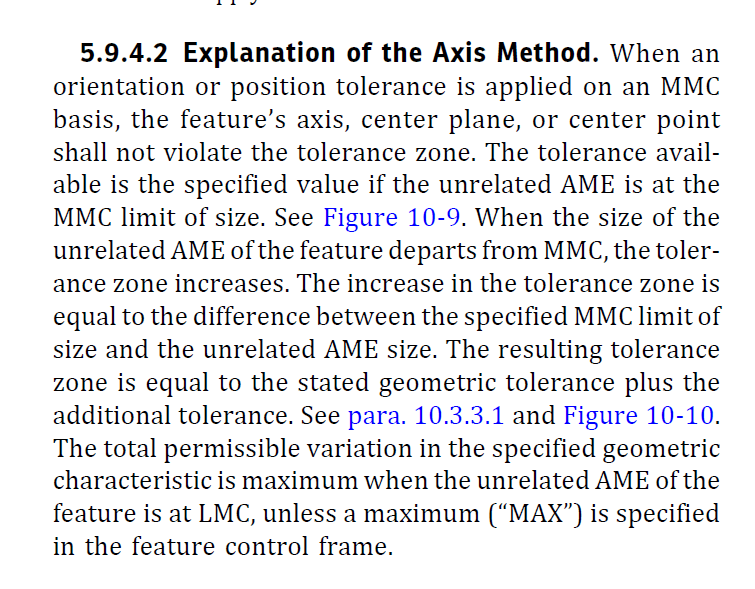
But as to your first question... by definition, the bonus tolerance is always limited to the difference between max and min diameters, according to ASME. There is a way to limit the bonus tolerance to be less than the difference between max and min diameters (paragraph 5.9.4.2 of ASME Y14.5), but no way to allow the bonus to be greater than that difference.
In the ISO standard there is a way to do so, called "reciprocity." But let's leave that off the table for now.

John-Paul Belanger
Certified Sr. GD&T Professional
Geometric Learning Systems
 
Yes you are right, I am sorry i got confused while giving the example. I have edited the post accordingly.

Could you help me and recheck the ASME clause that you mentioned. I cant seem to find the paragraph. A screenshot will work too.

I am very grteful for your help !
 
The reference I made to the ASME standard (2018 edition) is shown below -- it's the very last sentence in that paragraph, where they mention the option of stating a MAX to the geometric tolerance. That places a cap on the total geometric tolerance, including any bonus. (If you only have the 2009 version of that standard, it would be paragraph 2.8.2.)

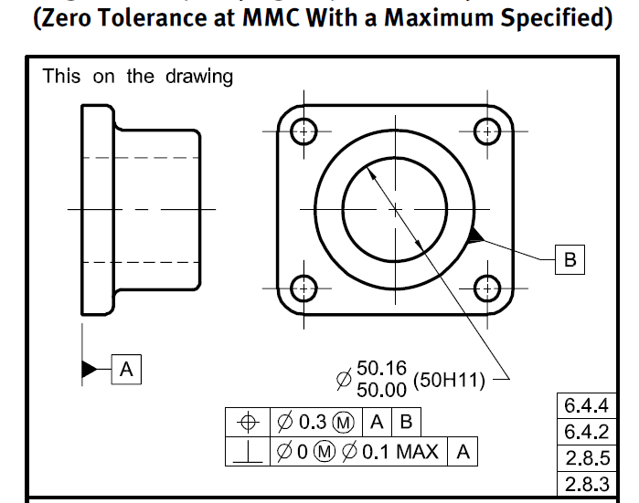
I've also included a screen shot from the ASME standard that shows an example -- the lower callout for perpendicularity allows a MAX of 0.1 (normally the perp tolerance would be allowed to grow to 0.16).


ASME1_dww3dj.png
ASME2_bl5ybq.png


John-Paul Belanger
Certified Sr. GD&T Professional
Geometric Learning Systems
 
Yeap understood !

Thankyou for taking the time to help me with this.

This was very helpful !
 
Status
Not open for further replies.

Part and Inventory Search

Sponsor