Eng-Tips is the largest engineering community on the Internet

Intelligent Work Forums for Engineering Professionals

  • Congratulations waross on being selected by the Eng-Tips community for having the most helpful posts in the forums last week. Way to Go!

Generating PM Diagrams for Concrete 2

Status
Not open for further replies.

sticksandtriangles

Structural
Apr 7, 2015
469
US
I am attempting to generate a concrete PM diagram tool and I am running into an odd bug, I am hoping someone can point me in the right direction.

A quick summary of where I am at, I have tool that allows the user to place concrete shapes and rebar on the screen.
After the user input is collected, a mesh and assumed strain profiles are generated for the concrete shape and rebar.

With the strain profiles and stress strain curves of the materials, I perform sum of forces in the vertical direction and sum of moments about the bending axis of interest.

Where the trouble comes in, I get differing moment results depending on where the shape is generated.

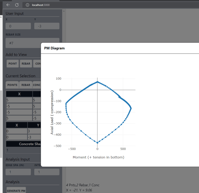
When the shape is generated with the center at 0, 0, I get the results I expect for a PM Diagram:
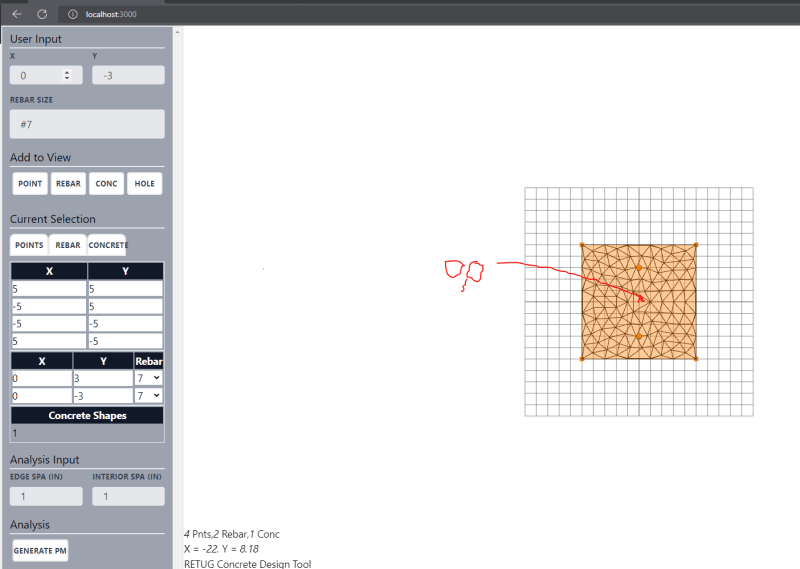
image1_d9mxti.png

image2_gf6pjd.png


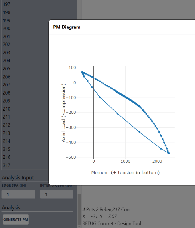
When the shape is generated with the center anywhere else, I get odd skewed moment results, but the same max tension and compression values:
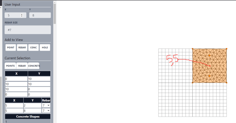
image3_hwzmp5.png

image4_wlxbij.png


I think my problem lies in where I am summing my moments about (notice that the max tension and max compression values match between the two diagrams, just the moment values are off). What point should I be summing moments about for an arbitrary concrete PM calculation? I thought it could be any point, as long as it was the same point, but that clearly is not working.

I have the code up on github if interested.

Code of interest:

JavaScript:
 //looping through each stress strain profile
  for (var strainProfile of strainProfiles) {
    let concForce = 0
    var steelForce = 0
    var concMoment = 0
    var steelMoment = 0
    for (var concEle of concElements) {
      concForce += concMaterial.stress(strainFunction(strainProfile[0],concEle.centriod.y, strainProfile[1]))*concEle.area
      //concMoment += -concMaterial.stress(strainFunction(strainProfile[0],concEle.centriod.y, strainProfile[1]))*(concEle.area*concEle.centriod.y-strainProfile[1])
      //concMoment += -concMaterial.stress(strainFunction(strainProfile[0],concEle.centriod.y, strainProfile[1]))*(concEle.area)*(concEle.centriod.y-concCentriod[1])
      concMoment += -concMaterial.stress(strainFunction(strainProfile[0],concEle.centriod.y, strainProfile[1]))*(concEle.area)*(concEle.centriod.y-strainProfile[1])

    }
  
    for (var steelRebar of rebarShapes) {
      //area times stress(strain)
      // this has been updated
      steelForce += Math.PI/4*(rebarDia[steelRebar.rebarSize])**2*steelMaterial.stress(strainFunction(strainProfile[0],steelRebar.geometry.attributes.position.array[1], strainProfile[1]))

      steelMoment += -Math.PI/4*(rebarDia[steelRebar.rebarSize])**2*steelMaterial.stress(strainFunction(strainProfile[0],steelRebar.geometry.attributes.position.array[1], strainProfile[1]))*(steelRebar.geometry.attributes.position.array[1]-strainProfile[1])

      
    }
    totalForceArray.push(steelForce+concForce)
    totalMomentArray.push(steelMoment+concMoment)
    
  }
  return [totalForceArray, totalMomentArray]
}


S&T -
 
Replies continue below

Recommended for you

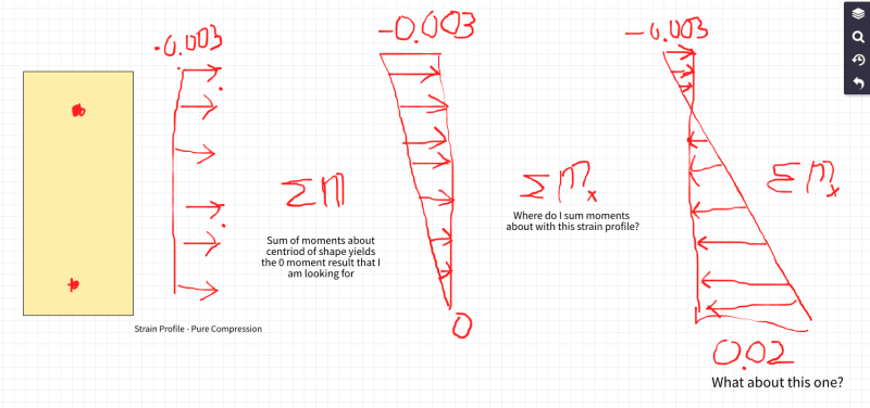
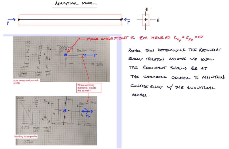
Just to help with discussion, here is what I am dealing with, I have a known strain profile, from which I can calculate concrete forces and steel forces.

image6_l2slk4.png


My struggles come in defining the point at which to sum moments about with differing strain profiles.

S&T -
 
Recommend summing moments about the geometric center as that is likely how the column would be modeled in an analysis package.

You can sum moments about any location but you need to include the effect of the resultant axial force.

I'm making a thing: (It's no Kootware and it will probably break but it's alive!)
 
You have to take the moments about the resultant force if you want the pure compression/tension cases to have zero moment on the diagram. This is at the gross section centroid for symmetric shapes with symmetric reinforcement, but may end up being elsewhere for non-symmetric cases, and different locations for pure compression and tension respectively. I'd fudge the tension calculation in that case since that part of the diagram is less frequently used.
 
Steve and I take different approaches. My base assumption is you want to directly compare the interaction surface results to the internal forces reported from an analysis program. We mostly model columns as bar elements between nodes where the bar is aligned to the centroidal axis of the unreinforced cross-section. Since the analysis model is going to report axial and moments about the geometric centroid it is much more convenient for the interaction curve to be built with the same basis, otherwise you would need to post-process applied loads to be about the same point your are summing moments about which would result in different moments showing up on the interaction plot vs what the user entered which will just invite confusion.

I'm making a thing: (It's no Kootware and it will probably break but it's alive!)
 
Celt83 said:
You can sum moments about any location but you need to include the effect of the resultant axial force.

I've got to think about including the effect of the resultant axial force, this is not intuitive to me.

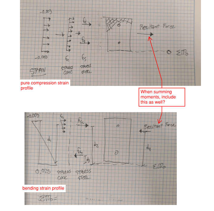
Are you saying that in addition to my concrete moments (force * distance) and my steel moments (force * distance), I need to take the resultant force and multiply by it's distance?

Capture_jul4bv.png


S&T -
 
yep

To work out the math do some back checks summing moments about the base inclusive of the resultant force and also summing moments about the resultant force location once the math is correct those two calcs will yield the same value.

For your typical beam since there is no axial load the sum of C = sum of T so the resultant = 0 which means for the case with no axial load it doesn't matter where your sum moments. Once there is a net axial load on the section then static equilibrium requires it to be included in the moment summation.

I'm making a thing: (It's no Kootware and it will probably break but it's alive!)
 
My base assumption is you want to directly compare the interaction surface results to the internal forces reported from an analysis program
Nah. The column will never see the N*-M* from the analysis. Make the calcs pretty.

On a slightly more serious note, you'll know it's right when the moment for a non-symmetric section is zero for pure compression.

One step further: my version of this has the origin for calculating moments as an input, so it can be either geometric or plastic centroid. Sticksandtriangles, you may as well do this while revising your program.
 
steveh49 said:
..you'll know it's right when the moment for a non-symmetric section is zero for pure compression...
I'd add this is only true if the reinforcement arrangement within the section is also symmetric about the centroid. Once you get into asymmetric reinforcement layouts both compression and tension peak values will include some moment capacity.

It all really comes down to what your reference frame for your moment computations is.

I'm making a thing: (It's no Kootware and it will probably break but it's alive!)
 
I was able to pin point my error, it was an error in my strain function generation.

Results seem to be inline with what I would expect now.

Symmetric sections give symmetric PM diagrams:

img1_b4fnn8.png

img1a_wbntnh.png


Nonsymetric reinforcement yields offsets

img2_bnjrkf.png

img2a_nresxl.png


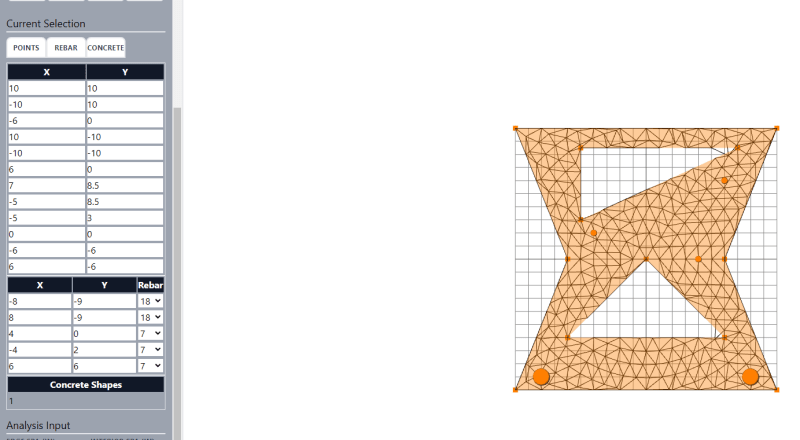
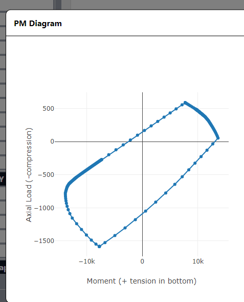
Odd shapes yield odd PM diagrams :)
img3_alpui3.png

img3a_lywdxj.png


Let me know if you see anything off in these diagrams, I appreciate your help!

I hope to get this stuff pushed up to the website this weekend so you guys can test it out and let me know of any troubles.

S&T -
 
Celt83 said:
I assume you are generating the P-M curve by just varying the neutral axis depth?

That is correct

Celt83 said:
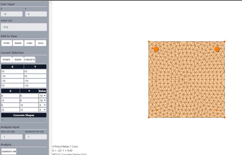
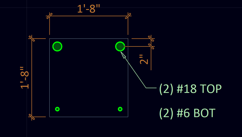
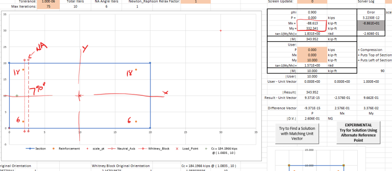
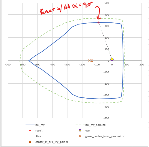
As an example your 20x20 with (2)#18 and (2)#6, for straight Mx bending with no Axial load you need the neutral axis to be on an angle:

I do not follow this statement, can you help me understand? Why does this shape and rebar pattern create a neutral axis on an angle?

Moving forward I plan on adding a MM graph and a 3d interaction surface, maybe it will be more clear as I progress.

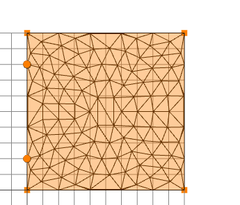
Just for clarity here is the shape we are talking about, 4000psi conc, 60ksi yeild:

Capture_lokoln.png


S&T -
 
yeah I botched it I had the 18's on the left and the 6's on the right. (deleted the earlier posts)

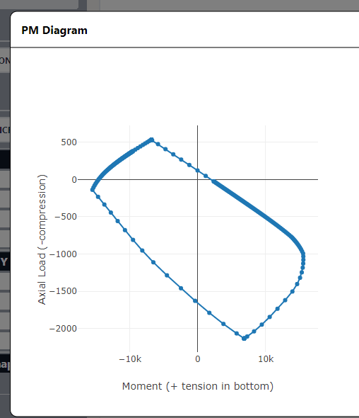
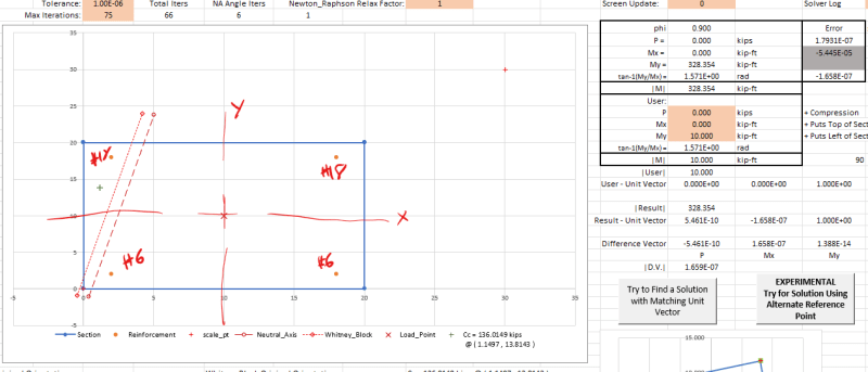
With the right setup Moment about the X-axis has the steel balanced so the neutral axis can remain horizontal without issue, but moment about the Y-axis the reinforcement is unbalanced so the neutral axis can't be held at 90-degrees and give correct results:
Screenshot_2022-09-23_112325_oqjk4j.png

Screenshot_2022-09-23_112454_yoxafr.png

Screenshot_2022-09-23_112533_hjjts4.png


I'm making a thing: (It's no Kootware and it will probably break but it's alive!)
 
Status
Not open for further replies.

Part and Inventory Search

Sponsor

Back
Top