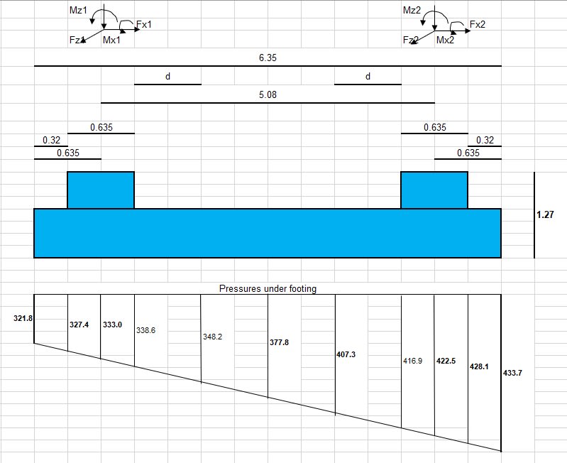
I need to draw bending and shear diagram for a combined footing.
I am trying to follow one example on net.


M1 at center of pedestal 1 = 1/2 x (333.0 + 321.8) x 0.635 x 0.635 / 2 x 2.54(foundation W) -62.27 x 1.27 + 569.44 = 658
M2 at center of pedestal 2 = 1/2 x (433.7 + 422.5) x 0.635 x 0.635 / 2 x 2.54(foundation W) + 62.27 x 1.27 - 227.78 = 658 = 70.55
The author calculate the Moment at mid span in such way:
M mid span = 377.8 x 5.08^2 / 8 x 2.54 + (M1 + M2) / 2
Can anyone advise why he calculated in this way?
moreover, can anyone help assist me how to draw the bending and shear moment for this foundation?
I am trying to follow one example on net.


M1 at center of pedestal 1 = 1/2 x (333.0 + 321.8) x 0.635 x 0.635 / 2 x 2.54(foundation W) -62.27 x 1.27 + 569.44 = 658
M2 at center of pedestal 2 = 1/2 x (433.7 + 422.5) x 0.635 x 0.635 / 2 x 2.54(foundation W) + 62.27 x 1.27 - 227.78 = 658 = 70.55
The author calculate the Moment at mid span in such way:
M mid span = 377.8 x 5.08^2 / 8 x 2.54 + (M1 + M2) / 2
Can anyone advise why he calculated in this way?
moreover, can anyone help assist me how to draw the bending and shear moment for this foundation?
