Continue to Site

Eng-Tips is the largest engineering community on the Internet

Intelligent Work Forums for Engineering Professionals

  • Congratulations waross on being selected by the Eng-Tips community for having the most helpful posts in the forums last week. Way to Go!

Purlin Splice

Status
Not open for further replies.

SteelPE

Structural
Mar 9, 2006
2,749
I have been asked to work on a project for a new client. The client currently owns a metal building that has been modified by a previous owner and my client is looking to restore the building to its original configuration. Code = IBC 2015.

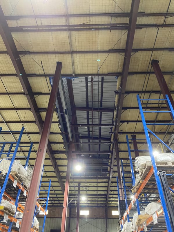
Modifications included the installation of a poorly designed independently framed penthouse in the middle of the existing building. The installation of these penthouse also included removal of existing purlins under the penthouse. When the penthouse was installed, someone thought it was a good idea to cut the roof purlins off flush with the mainframe. The existing purlin system are back-to-back C’s lapped 25” on each side of the mainframe. Now, I have the pleasure of figuring out how to repair this.

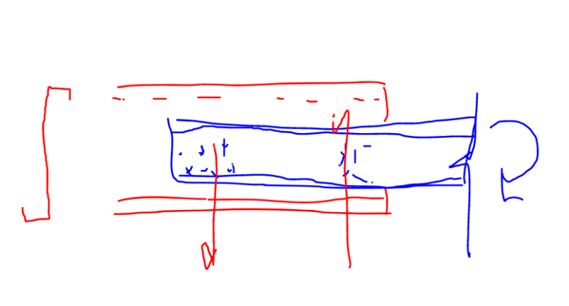
I have an idea to remove any existing laps that are still be installed above the mainframe (the leftover tail sections from the original splices) and then add a new hot rolled channel as a splice between the new and existing purlin (see sketch). The idea would be to transfer the moment from one section of purlin to the next through this new hot rolled section.

The issue I have is that I have no idea how to design this moment splice. I was thinking of using the elastic method of bolt analysis, but that method allows for an applied load at an eccentricity (essentially a moment) and I am not sure if this is the correct procedure for this type of splice.

How do you go about figuring this type of moment splice?
 
 https://files.engineering.com/getfile.aspx?folder=10c37421-5617-4700-94a6-c6c30ff41b80&file=Proposed_Detail.pdf
Replies continue below

Recommended for you

I like discretizing the connection -- if only in my head -- as a pair of connection groups that form the moment resisting couple.

When all is said and done, it might be more economical to just do a full sistering of the purlins with channels such that the purlins work simple span.

C01_ksglrk.png
 
In your sketch, the design shear in the bolts-screw = moment/(distance between the bolt-screw groups)?


KootK said:
it might be more economical to just do a full sistering of the purlins with channels such that the purlins work simple span

I thought about that, but I'm not sure how much I can "sell" to the client. Full sistering seems like a good idea however, I can't get the existing purlins to work by adding an additional simply supported purlin in-between the new and the existing... I would have to add two additional purlins.

Another option would be to abandon the existing purlins all together and add new simply supported purlins in-between the existing such that the new purlins could carry all of the load. Again, going to be a tough sell to the client.


The client isn't dumb, I just need to make sure I have vetted all of the solutions I can think of so I can answer his questions when he asks.
 
SteelPE said:
In your sketch, the design shear in the bolts-screw = moment/(distance between the bolt-screw groups)?

Yes for purely moment transfer. You'll need to consider the demand for shear transfer across the joint as well of course.
 
Kootk said:
I like discretizing the connection -- if only in my head -- as a pair of connection groups that form the moment resisting couple.

That’s how our cantilever purlin stub detail works. The bolts are 300 apart length ways. That’s for short cantilevers though.

SteelPE said:
The idea would be to transfer the moment from one section of purlin to the next through this new hot rolled section.

How come hot rolled? Why not another purlin, with a long lap onto each original purlin. Bolts say 900 apart.
 
Metal Building guy here. Your approach is what I would do.

The original design used the laps to create a continuous end condition of the purlins and also made the bending and shear strength at the lap as strong as both original purlins combined. So the channel you design needs to be strong enough to do those two things. Without knowing the design moment, as long as you make sure it laps as long as the original laps and has greater section properties, you'll be good. Keep in mind that cold formed purlins are usually 55 ksi so some adjustment needs to be made if you're using a lower grade channel.

Much harder to design the connections without knowing the moments but I don't think you need to. If the original connection has two 1/2" A307 bolts at the center and then (2) 1/2" A307 bolts at each end of the lap, you can feel good that works. Maybe throw in extra bolts like you've shown for redundancy. If you really want a moment calc, make some basic load assumptions about wind, snow and uplift and create a line load. Analyze the purlin as a beam with fixed ends and design your connection for that moment with a healthy amount of extra capacity.

The thing I'm curious about is the purlins that you're adding back in. Were they originally attached to a through fastened roof? If they were, they used the AISI equations to both brace the top flange from lateral movement but also to brace the bottom flange using the panel as a torsional restraint. If through fastened roof isn't back over the top, those purlins will need discrete bracing for LTB. If it's a standing seam roof, the rest of the purlins should already have discrete bracing that you can just copy.
 
This is part of what I am dealing with. The entire penthouse is being removed and the building is being resorted.

IMG_1581_agtwhh.jpg


SandwichEngine said:
Without knowing the design moment, as long as you make sure it laps as long as the original laps and has greater section properties, you'll be good. Keep in mind that cold formed purlins are usually 55 ksi so some adjustment needs to be made if you're using a lower grade channel.

The moment at the mainframe was indicated on the sketch... Ma= 106 inch-kips.

Yes, it's a thru fastened roof, but we will be infilling the existing roof with metal decking wo LTB of the top flange is not an issue, but will more than likely be installing bridging (pieces of metal studs) at the 1/4 points.

SandwichEngine said:
Analyze the purlin as a beam with fixed ends and design your connection for that moment with a healthy amount of extra capacity.

I am using the current code required snow loads. In my area, the required snow load is 35psf, so I am not overly worried about wind.
 
can you just simple span some channels from frame to frame? what am I missing?
 
JStructsteel said:
can you just simple span some channels from frame to frame? what am I missing?

Yes, simply supported members are possible... However, the end fixity condition has now changed in the adjacent bays which will need to be addressed as well by adding more simply supported purlins. So quickly, the project grows... and there are two of these openings.

Not to mention the horizontal X bracing that was removed and needs to be replaced.... and the stability bracing as well. The original owner made a real mess of things.
 
Gotcha. Can you check the existing purlins for the simple span or two span condition they are in now?

Or match the connections they have there now?
 
JStructsteel said:
Gotcha. Can you check the existing purlins for the simple span or two span condition they are in now?

Or match the connections they have there now?

Existing purlins do not work as simply supported... They don't even work as simply supported for 1/2 the load. I would need to have any new simply supported purlin take all the new load.

Can't match the connections when they cut off the laps next to the mainframe. So my new hot-rolled channel has to take 100% of the bending load above the mainframe.
 
Status
Not open for further replies.

Part and Inventory Search

Sponsor