Continue to Site

Eng-Tips is the largest engineering community on the Internet

Intelligent Work Forums for Engineering Professionals

  • Congratulations waross on being selected by the Eng-Tips community for having the most helpful posts in the forums last week. Way to Go!

Aligning holes on center of spline teeth for a spline sleeve

Status
Not open for further replies.

rollingcloud

Aerospace
Aug 9, 2022
167
US
Capture111dd_vyicxz.png

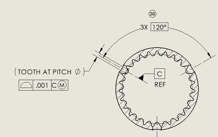
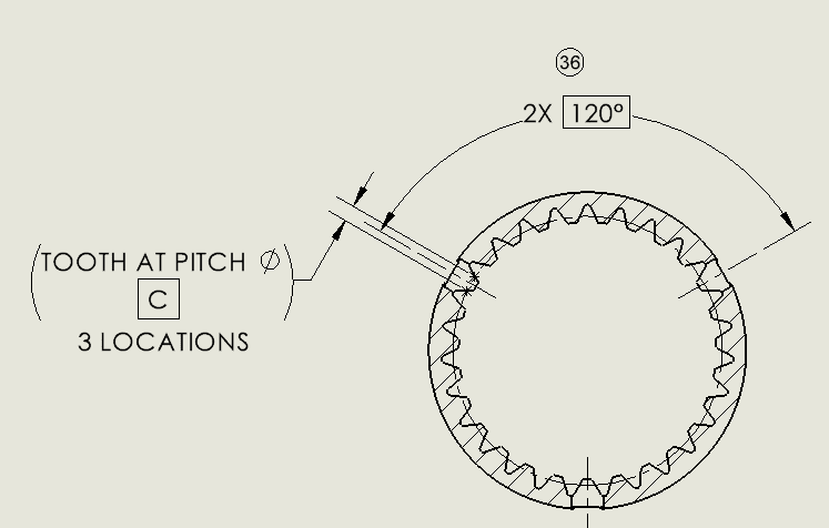
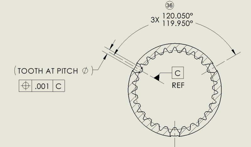
I am trying to align the holes on the center of the spline teeth, currently I have the hole axis as datum C, I am thinking either applying true position on the teeth with respect to datum C, or set 3 midplanes of the teeth as datum D and have concentricity between datum D & datum C, unsure about either of them, how would you go about this? I am assuming setting PD as a datum would make the part very difficult to inspect
 
Replies continue below

Recommended for you

I know there are standards for involute splines that don't mention it and standard practices that don't utilize it, but could you get away with applying profile of a surface with datum references to the geometry of the spline teeth? The profile value (or values) could consider all the dimensional requirements. If you could do that in your company, you could use the pattern of 3 holes as a "clocking" datum - the tertiary datum reference or the secondary out of two, that would lock a rotational degree of freedom about the gear axis for the entire pattern of teeth, and thus center those specific teeth to the holes. If used as a datum reference, it would be preferable to reference 3 holes at MMB to allow easier inspection, if datum shift is tolerable. If done this way, the directly toleranced 119.95-120.05 angle would have to be replaced by 120 basic and the holes should be controlled by position with ref. to the higher precedence datum features.
 
You mean using profile to control the teeth's flanks profile with respect to hole axis (datum C)?
Something like the snip below?
Capture111dd_wjzzdu.png


Can the teeth be datum C and place a true pos on the hole with respect to datums A, B & C?
Capture111dd_gcaxlg.png

But I am not sure in this case, what exactly is datum C? the center line of teeth?
 
rollingcloud,
What I meant is to create a datum reference frame that will fully constrain the tolerance zone for the entire crown of teeth, and by that the 3 specific teeth that need to be centered to the holes will need to be controlled correspondingly.
The datum feature selection should be based in functionality.
Here is a full suggestion:
The OD of the part could be datum feature A, and it would provide a datum axis and the simulator of it would constrain 4 degrees of freedom. The pattern of 3 holes will be datum feature B referenced at MMB, and its simulator (3 fixed size pins) will constrain the remaining 2 degrees of freedom, including the rotation about datum axis A, and providing a datum which is 3 axes and a point. Datum axis A will define 2 perpendicular planes of the datum reference frame intersecting at it, and the three axes of datum B will lie in the third plane. The three datum reference frame planes will form the axis system for measurement.
The entire geometry of all teeth could be specified by basic dimensions. A surface profile tolerance feature control frame would point by a leader to the outline of one of the teeth with an all-around symbol, and this will require all teeth to fit in the tolerance zone. The tolerance value could be adequately tight to control the size, form, orientation, and location requirements of all features forming the crown of teeth. Alternatively, if different tolerances are preferred for different groups of features, there could be several feature control frames with the number of places indication, all referencing datum features A primary and B secondary and thus bounded by a simultaneous requirement. The three teeth that need to be centered to the 3 holes that are datum feature B will need to conform to a tolerance zone that governs it - because the rotation around datum axis A is locked by the pins simulating datum B which is associated with these holes.
 
Status
Not open for further replies.

Part and Inventory Search

Sponsor

Top