Hi everyone,
Looking to get advise/comments on the following.
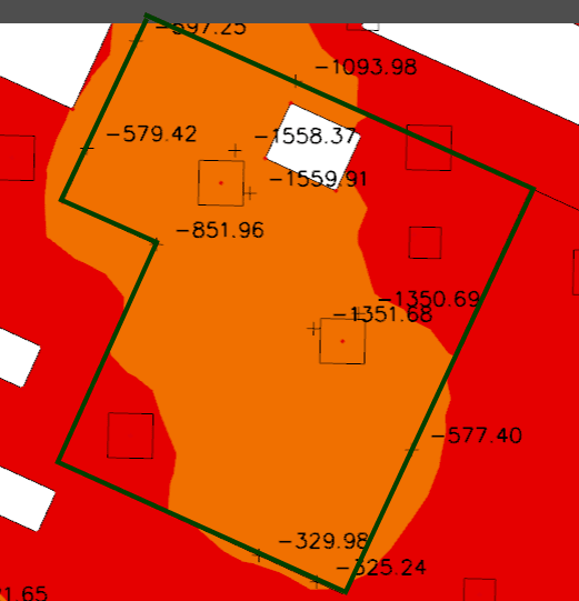
In the attached image, inside the green thick line is a 800mm slab and on the outside is a 300mm slab. The orange represents the moment capacity of a 800mm slab. As you can see some parts of the 300mm slab technically are required to be 800mm due to the moments 'spilling'. When I increase the extent of the 800mm slab to capture this, the moments 'run away' and the slab extent is required to get bigger and bigger. The question is, is there a way to justify the moments spilling and parts of the 300mm slab being over the moment capacity? Otherwise the extent of the slab gets excessive.
Looking to get advise/comments on the following.
In the attached image, inside the green thick line is a 800mm slab and on the outside is a 300mm slab. The orange represents the moment capacity of a 800mm slab. As you can see some parts of the 300mm slab technically are required to be 800mm due to the moments 'spilling'. When I increase the extent of the 800mm slab to capture this, the moments 'run away' and the slab extent is required to get bigger and bigger. The question is, is there a way to justify the moments spilling and parts of the 300mm slab being over the moment capacity? Otherwise the extent of the slab gets excessive.