Continue to Site

Eng-Tips is the largest engineering community on the Internet

Intelligent Work Forums for Engineering Professionals

  • Congratulations SSS148 on being selected by the Eng-Tips community for having the most helpful posts in the forums last week. Way to Go!

Question on Parallelism/Perpendicularity

Status
Not open for further replies.

Crux_1

Mechanical
Dec 6, 2022
3
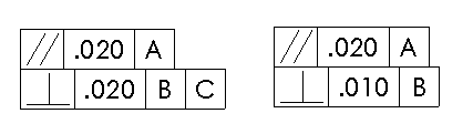
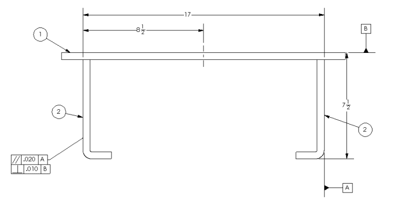
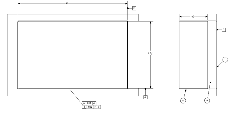
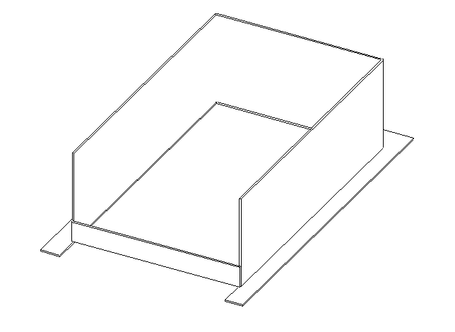
I'm pretty new here and still learning GD&T. In the imagine, I've seen both these GD&T call out recently. I was looking if anyone wants to walk me through this. To me I thought this would create redundancy and if there is a better way to go about this. I apologize in advice if this is a dumb question.

GDT_djdald.png
 
Replies continue below

Recommended for you

"if there is a better way to go about this" - not without a description of the necessary outcome. If you had that description you would know if the existing callouts are useful.

It's a great question that is unanswerable from lack of information.
 
If A and B (and C?) are directly controlled for orientation (and location if applicable) relative to each other, and are being used in other geometric controls as the primary, secondary (and tertiary?) datum features in the same datum reference frame, it may be better to specify angularity/perpendicularity with ref. to |A|B| (or |A|B|C|).
 
Crux_1,

Can you show us a drawing with those specifications? Context can matter a lot.

--
JHG
 
I made two quick drawings to try and capture what is going on in the project. In the one with the parallelism of .020 with datum A and perpendicularity of .010 datum B. This would matter with another plate attaching that extends further down.

The other image it matters with what goes through.

Both of these are sheet metal parts. I wish I can show more of explain more but I hope this helps get an idea.

GDT1_o51544.png
GDT_2_z4qywj.png
 
In the first example - they are applied independently and the surface must meet each constraint. Obviously there could be a problem if datum feature A is not perpendicular to datum feature B; there should be some feature control frame supplying that constraint.

In the second example - I have no idea what's going on there since the left most view seems to be missing an edge line. Every time, rather than just showing a limited set of orthographic views, include a trimetric. If a reader cannot tell what feature the datum symbol is applied to it's not a good drawing.
 
Thanks 3DDave.

So, in the first example. Here are some of questions. I'm still new to GD&T. I'm just trying to make sure I can get a full grasp on everything going on.

1. When you say having a feature control frame supplying the constrain. Are you saying having a perpendicularity control the datum B? If you are saying that if datum B is controlled by perpendicularity, can you have the other face just be controlled by datum B to be parallel?
2. So I know the top is controlling location and orientation. The second is constraining the location and orientation. Is there ever a case of too much in a simple scenario like this?
3. Can't we just have the top face be datum A. Then those two faces just being perpendicular to Datum A?
4. Before I start getting annoying with questions haha. Can you just have rule 1# applied on drawings and tolerance just tighter without using a symbol on something like this.

As far as the example 2. I made a trimetric view of it.

gd_t_3_bnaian.png
 
Not seeing how adding a secondary datum to perpendicularity improves anything.
 
The Tick said:
Not seeing how adding a secondary datum to perpendicularity improves anything

Yes, it does. Will make the tolerance zone more stable. Y14.5 standard has some example where this concept is shown and explained.
 
For example 1:

Imagination time.

Is it possible for the controlled surface to be perpendicular to datum B and not be parallel to datum A? Of course.
So there is a requirement to also be parallel to datum A.
But what if datum feature A is not Perpendicular to datum B and vice versa.

Then the controlled surface can either be perpendicular to datum B or parallel to datum A but if datum A is far enough from perpendicular to datum feature B, then the controlled surface cannot meet both requirements at the same time. It also fails if the controlled surface is insufficiently flat.

If parallelism control is far more important then it can be smaller than the perpendicularity requirement. The reverse relationship is also possible.

So much would be easier to see if a couple of representative pieces of cardboard and some requirements for the relationship was available.

In the second example - I cannot tell what surface is used for datum feature A.
In the perpendicularity - I would likely use C and then B in that reference frame because the datum feature B is unlikely to be the most important one in this situation. Again, the requirements for the relationship aren't available.
 
TheTick said:
Not seeing how adding a secondary datum to perpendicularity improves anything.

greenimi said:
Yes, it does. Will make the tolerance zone more stable.

Rather than saying that it would make the tolerance zone "more stable" I would say it will make the difference between partially defined orientation (unstable tolerance zone) to fully defined orientation (completely stable tolerance zone in rotational degrees of freedom).
For example, If per the design intent a feature has to be perpendicular to both datum features A primary and B secondary (while A and B are also mutually perpendicular), then when only A is referenced in the perpendicularity feature control frame, the feature can be produced sufficiently perpendicular to datum feature A (within tolerance), but at say - 45° to datum feature B, and it will be considered just fine.

By referencing a primary and secondary datum features in a perpendicularity or angularity FCF, it is possible to replace 2 different measurements in 2 different inspection set-ups by just one, and reflect the functional assembly constraints better.
 
Status
Not open for further replies.

Part and Inventory Search

Sponsor