Continue to Site

Eng-Tips is the largest engineering community on the Internet

Intelligent Work Forums for Engineering Professionals

  • Congratulations KootK on being selected by the Eng-Tips community for having the most helpful posts in the forums last week. Way to Go!

Critical Section for Shear in a RCC Cantilever Beam 1

Status
Not open for further replies.

Skay999

Structural
Dec 7, 2022
6
Hello,

I am working on designing a RCC cantilever beam and this is probably a very beginner's question but I am trying to understand where the critical section is for a RCC cantilever beam. Would it be at the face of the support because there is no compressive force from the support? I have seen some examples online that use the max shear value at a distance d from the support but this doesn't seem right. Any thoughts?

Thank you
 
Replies continue below

Recommended for you

A beam being a cantilever does not mean that there is not compression in the end region of the beam. Whether there is compression near the end depends on how the beam is supported (column vs side of girder) and how it is loaded (top vs bottom). Check out ACI 318-19, Commentary R9.4.3.2 for examples of when you have to check shear at the face of the support.

The idea is that any load that is on the same side of the diagonal crack as the support will be transferred directly to the support by compression instead of through shear. If you look at the examples with that in mind, they should all make sense.

Structural Engineering Software: Structural Engineering Videos:
 
The way ACI has chosen to word that provision is horribly confusing.

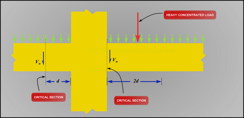
For a typical RCC cantilever, loaded from the top and supported from the bottom, yes, the critical shear can be taken at a distance d from the support.
 
I’m still kind of confused. Say it was connected to a girder, would there still be a compressive force. I attached a picture from the code, and wouldn’t this case be similar to a RCC cantilever beam?
 
 https://files.engineering.com/getfile.aspx?folder=7d6ea7c1-a418-45a0-a559-cb6ee941d6ab&file=02457414-DCA8-4C96-BE59-E14E176DDF7D.jpeg
Skay999 said:
Say it was connected to a girder, would there still be a compressive force.

If the beam frames into the side of a girder of equal depth, there would not be compression in the end region in the direction of the applied shear since it is not supported at its bottom. (If the beam cantilevered over the top of a girder, then there would be compression.)

Skay999 said:
I attached a picture from the code, and wouldn’t this case be similar to a RCC cantilever beam?

The example you attached has tension at the support, not the required compression, so the critical section is at the face of the support.
 
Great! This makes sense now. Thank you.
 
ProgrammingPE said:
If the beam frames into the side of a girder of equal depth, there would not be compression in the end region in the direction of the applied shear since it is not supported at its bottom.

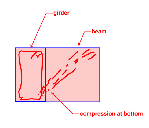
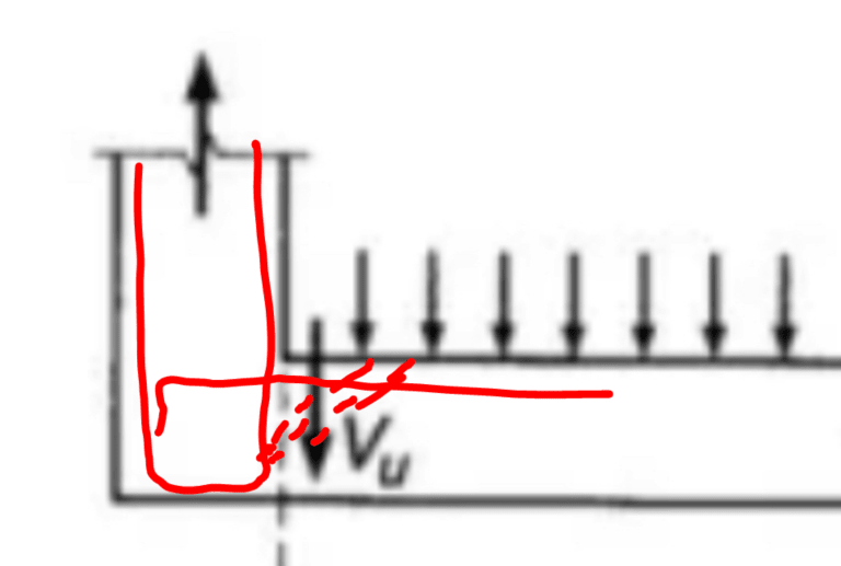
I disagree per the sketch below. The intent of hanger steel in the girder is precisely to provide a path for that last compression strut at the end of the beam.

c01_nmzza6.png
 
Interestingly, one could make the same argument for the hanging situation so long as the hangers are detailed properly. Obviously, the code says what it says and we're not going to go rogue on that unless there's a compelling reason to do so.

c01_tlxg8k.png
 
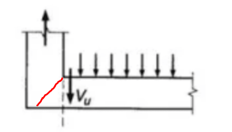
Taking the shear right to the face of the support only really makes sense to me when considering a hanger support that has no properly designed hanger bars. In that case, we'd be anticipating the shear crack shown below. But, then, who would be foolish enough to do that?

c01_syjdtj.png
 
I kind of understand what you are saying, but I’m guessing the code specifies different critical sections for a reason. Also, wouldn’t it be more conservative to always take the higher shear value produced at the support location (for simply supported and cantilever beams) when designing the stirrups for a member? I don’t know how it works in the practical world because I’m still a student, but does designing for a shear value at a distance d from the support yield significantly different design?
 
Skay said:
Also, wouldn’t it be more conservative to always take the higher shear value produced at the support location (for simply supported and cantilever beams) when designing the stirrups for a member?

ordinarily yes, because the shearing force is usually slightly higher at the support.

Skay said:
but does designing for a shear value at a distance d from the support yield significantly different design?

Not usually, but it can make a difference.

The idea is as ProgrammingPer said, "that any load that is on the same side of the diagonal crack as the support will be transferred directly to the support by compression instead of through shear". It's based on the observation that shear cracks form at ~45 degree, and thus the loads within that 45 degree line go straight to the support. I'm not a huge fan of the assumption myself. I don't know why anyone would skimp on this final zone, which is where slabs and beams tend to fail in practice.
 
I think if we think about the rebar detailing it may help visualize this thought.

The design shear is the value used to calc the required stirrup steel. That is it.

This does not mean we ignore placing stirrups in the compression bulb at the end of the beam (d or dv whatever it is..). It just allows us to relax the spacing and size of the steel in that area.
 
Wrantler said:
this does not mean we ignore placing stirrups in the compression bulb at the end of the beam (d or dv whatever it is..). It just allows us to relax the spacing and size of the steel in that area.

Some softwares do this though. I just tried some experiments and calibrated the slab to require no stirrups at point “d”, and then I added more load within the end zone, producing massive shear stress. Software still say no stirrups. As indeed a strict reading of the codes can allow.

It’s weird too that they allow “d” as the critical section, when stirrup rules are based on d/2. Why are we allowed a big jump of “d” home to the support when we can only take smaller steps of “d/2” elsewhere?
 
Interesting Tom. I do not use softwares to do design...only the analysis (use my own spreadsheets for design). Somewhat for reasons like you mention.


For my own information as much as skay's, what does the crack formation actually look like in the cases where the critical section is at the face? The website offers little in the way of explanation and would be great to have.

----------------------------------------------------------------------

Why yes, I do in fact have no idea what I'm talking about
 
Status
Not open for further replies.

Part and Inventory Search

Sponsor