caiomarcon
Civil/Environmental
Stability of Steel Truss during Lifting
I'm studying about stability of steel trusses during lifting (I usually call suspended trusses): Design and Analysis on Out-of-Plane
Does anyone have any reference (book, standard or design guide) to suggest me?
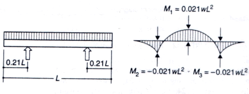
I have a lot of doubt about the unbraced length of the chords. Is it correct to consider the total length of the chord or the distance between lifting points?
My question is about design for stability, not practical field experience
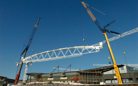
I'm studying about stability of steel trusses during lifting (I usually call suspended trusses): Design and Analysis on Out-of-Plane
Does anyone have any reference (book, standard or design guide) to suggest me?
I have a lot of doubt about the unbraced length of the chords. Is it correct to consider the total length of the chord or the distance between lifting points?
My question is about design for stability, not practical field experience
![[smile]](/data/assets/smilies/smile.gif "[smile] [smile]") . But based on the figure I think there are possibilities for horizontal support.
. But based on the figure I think there are possibilities for horizontal support.