Continue to Site

Eng-Tips is the largest engineering community on the Internet

Intelligent Work Forums for Engineering Professionals

  • Congratulations KootK on being selected by the Eng-Tips community for having the most helpful posts in the forums last week. Way to Go!

Collector Force Diagrams

Status
Not open for further replies.

StrEng007

Structural
Aug 22, 2014
510
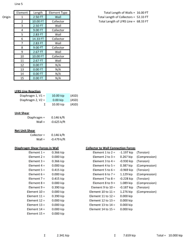
I ran a collector force diagram against a line of shear walls/collectors and got the overall diagram to balance out to zero at the end of the resisting line.

However, the connection forces for the collectors do not change signs in some locations (each end has the same positive or negative value).

I'm used to seeing the collector have compression at one end and tension at the other (or the reverse when wind loads are reversed). Does this mean the diagram is wrong even though the total loads balance out to zero? How should I handle a collector with end connection forces in the same direction for each segment?
 
Replies continue below

Recommended for you

It could just be a strut, passing the load through the member from one location to another, thereby having compression or tension at each end. Possibly. But as Agent indicated, sketches/pics and some load values would help.
 
As jayrod12 intimated, there is no hard rule that a collector's end reaction ought to change sign between ends. In general, that will not be the case. What's important is that the numerical difference between the axial reactions at the member ends equals the net sum of the shears that the attached diaphragm(s) exert on the collector element between the ends.
 
Here is the collector force diagram for this scenario. A couple things to note:

1. Top of walls are tied together with a continuous tie-beam.
2. Walls are 8" CMU.
3. Lateral forces are due to wind. For simplicity a unit load of 10K is used in this illustration.
4. Building is single story with a flexible diaphragm.

I realize that lateral load will be distributed to these walls based on their relative rigidity. I have run a separate calculation to distribute the 10K load based on rigidity, R= 1/[0.1(H/D)³ + 0.3(H/D)]. This even accounts for the very short segments of wall (elements 5 and 6).

However, it's my understanding that even though we use relative rigidities, the collector (tie-beam) still needs to allow the forces to flow through the top of wall. For this, I've considered "collector segments" for the locations where tie-beams span over openings.

Regarding my OP... take the collector over opening #2. There is a tension load on the left side of the collector which PULLS wall element #1 to the right. On the right side of the collector is a compression load that PUSHES wall element #3 to the right. This is the sort thing I'm used to seeing.

Now take the collector as it spans over element #4. Both sides of the collector are in tension. I would understand this to mean the left side of collector #4 is pulling wall element #3 to the right. However, the right side of collector segment #4 is also in tension. So is it pulling wall element #5 to the left? This sort of counteracting force doesn't seem correct.
 
 https://files.engineering.com/getfile.aspx?folder=dc6223e0-ff88-4b6e-b22e-369f83119cae&file=Collector_Diagram.pdf
Your total diaphragm forces don't equal 10 kips. How did you model this? There seem to be errors in logic.

Regardless, for such a simple system and just 10 kips I would try to use the two long walls (only) rather than over-complicate the analysis.

 
I don't exaclty know how you are going about the process here.... but just looking at your sketch, I am guessing that the loads are being distributed to piers based upon their stiffness (basically some form of bd^3/12 for each wall segment). I would guess that walls 3 and 11 are tending to attract more load than walls 5 7 and 9.... therefore it would be possible for the load to bypass these wall and head towards the other stiffer walls... hence the odd tension/compression scenario you are seeing.
 
JLNJ,
I noticed the same thing... the total forces in the system don't equal the original shear put into the resisting line. I've used this spreadsheet against textbook examples and achieved identical answers. It seems like the layout of these walls is causing an error. To add to the confusion, notice how the diagram finishes at zero (very close) at the end of the last wall segment. This is usually my first check to make sure the end of the resisting line is in equilibrium.

I've attached an image of the same spreadsheet producing correct results for another lateral resisting line with many wall segments and collector segments.

Note the following:
1. Diaphragm shear applied to the line equals the total forces in the walls. It maintains the total forces as you mentioned.
2. Each connector segment has end reactions that are either compression or tension. They pull at one end and push at the other end.
Collector_Diagram_v.3_i7tpm7.png


SteelPE,
The calculations you saw in the original PDF don't have anything to do with wall rigidities. I ran those numbers as a separate check. What the original PDF is showing is the distribution of forces to the walls based on the collector force diagram.
 
StrEng007 said:
Regarding my OP... take the collector over opening #2. There is a tension load on the left side of the collector which PULLS wall element #1 to the right. On the right side of the collector is a compression load that PUSHES wall element #3 to the right. This is the sort thing I'm used to seeing.

Now take the collector as it spans over element #4. Both sides of the collector are in tension. I would understand this to mean the left side of collector #4 is pulling wall element #3 to the right. However, the right side of collector segment #4 is also in tension. So is it pulling wall element #5 to the left? This sort of counteracting force doesn't seem correct.

Rather than think in terms of the collector pushing / pulling the wall, think in terms of the diaphragm trying to move in one direction and the walls pushing back to oppose that movement. With multiple walls of varying stiffness, the shorter walls can't "push back" with the same magnitude of force that the longer walls can. Therefore, the short walls only push back a little bit; they reduce the axial force in the collector, but they don't overcome the collector force completely.

Imagine walking up to a column and grabbing it at waist height while lifting up. You've reduced the column compression below your hands, but there's still a net compression on the column. That is what's happening at the shorter walls in your sketch.
 
How are you calculating the "Collector To Wall Connection Forces"? What is the formula in your spreadsheet?

When this spreadsheet is working "correctly", does it match the separate spreadsheet you said that you have that distributes forces to the shear walls based on rigidity/length?
 
I'm still not sure how you are calculating the "Collector To Wall Connection Forces" in your spreadsheet, but it seems to be distributing the loads to the shear walls correctly (see attached mark-up of your diagram with forces summed for each shear wall segment, sorry for the small/messy handwriting).

[URL unfurl="true"]https://res.cloudinary.com/engineering-com/image/upload/v1672860967/tips/Collector_Diagram_sum_forces_c4odpl.pdf[/url]
 
I see now how you are calculating the "Collector to Wall Connection Forces". Initially, I totally missed the diagram above the sketch, but now that I see it, I see how you are summing the forces.
 
gte,
Thanks for taking the time to write this out. I noticed that your sum of forces for each of the shear wall elements add up to the 10K load. This is what I was saying earlier, the diagram balance out. My question is how the collector force diagram remains on the tension side of the diagram as it transitions over multiple openings.

Notice how the load in element #3 has the combined effect of collector #2 pushing the wall to the right and collector #4 pulling the wall to the right.

Now take the collector element #6 as it attaches to shear wall element #7. The force is in tension, meaning it's pulling shear wall element #7 to the left. I'm not sure how this force has that direction when the entire line is trying to move to the right.

If you haven't looked already, check out the image I uploaded for another scenario. It doesn't have the issue as described above.
 
Deker said:
Therefore, the short walls only push back a little bit; they reduce the axial force in the collector, but they don't overcome the collector force completely.

Thanks for this explanation. It makes sense in terms of the overall numbers.

Question:
Let's say this line was entirely framed out of wood structural panel segments (ignore aspect ratio limitations) and we utilize a non-continuous beam that ONLY spans over the openings and attaches to the top edge of each shear wall. This beam will act as a collector. When you attach collector #4 to shear wall #5, is there tension across that joint? Logic says No, it should be a positive connection where the beam pushes into the shear wall (compression).

My understanding on this has always been that the force seen in the collector force diagram is the one you use to connect collectors to walls etc. If you run numbers for most typical collector force diagrams, you will find each collector has opposite force directions at each end.
 
In your wood wall scenario, you'd be distributing the loads differently based on your description. That would be more of a tributary area type distribution instead of a stiffness distribution if the collectors couldn't pull on the connections as well as push.
 
The wood wall scenario is taken from the Breyer's Wood Structures book. In that text, they apply the same theory behind the collector force diagram.

Wood walls will distribute based on relative lengths. If you had a resisting line constructed as Collector / Shear Wall / Collector, it's obvious that 100% of the lateral load goes into the wall.

If you had 10K going into a resisting line constructed of 20 FT Shear Wall/ 10 FT Collector/ 20 FT Shear Wall, then each wall would take 50% of the load.
Each wall would have 4K from the diaphragm, with an additional 1K point load coming off the end of the collector (5K per wall).

Like I mentioned before, I ran a stiffness/rigidity check on the side. But my main question is focusing on the collector forces.
 
KootK said:
What's important is that the numerical difference between the axial reactions at the member ends equals the net sum of the shears that the attached diaphragm(s) exert on the collector element between the ends.

Any texts to read up on this? Breyers doesn't address this.
 
StrEng007 said:
Question:
Let's say this line was entirely framed out of wood structural panel segments (ignore aspect ratio limitations) and we utilize a non-continuous beam that ONLY spans over the openings and attaches to the top edge of each shear wall. This beam will act as a collector. When you attach collector #4 to shear wall #5, is there tension across that joint? Logic says No, it should be a positive connection where the beam pushes into the shear wall (compression).

You wouldn't be able to stop the collector at Wall #5. It would need to be continuous through the wall. Any splices made in the collector would be designed for the force in the axial diagram.

StrEng007 said:
My understanding on this has always been that the force seen in the collector force diagram is the one you use to connect collectors to walls etc.

That's correct. What makes you think otherwise in this case?
 
Deker said:
That's correct. What makes you think otherwise in this case?

I'm not sure if the point of my original post is getting lost here.

My main question is about how to handle collector segments that "don't change signs". I'm not saying this wrong but it's the first time I'm seeing it with this scenario.

For anyone who's willing to try out the numbers, given the scenario in the original PDF, if there was a splice in the collector at the joint between Collector #4 and Wall #5, would it be in tension or compression? And if it's in tension, please explain why an entire lateral force pushing from left to right creates tension at this joint? Same goes for joint #6 to #7.


I am not sure if I am missing something here or if I am. Do you really know how your spreadsheet works? How is the 10 kips being distributed to the collector? Are all 10 kips placed at the end of the wall as shown, or is the collector truly a collector and pulling the 10 kip load from a diaphragm that runs the entire length of the structure?

I have your entire structure around 68' long and understand this system as being a collector.... meaning the 10kips would be distributed to the collector by the diaphragm at a rate of 10kips/68feet = 147 plf...... The load built up between walls 3 and 11 would be the distance between the two walls multiplied by 147 plf =4,483# between walls 3 and 11 moving to the right...... Wall 3 would be seeing the load moving away from it (tension) wall 11 would see the load moving towards it (compression)..... if wall 5 and 7 only attracted a small % of the overall load (because they are small and not as stiff as the other walls) then their reduction of the overall 10 kips would be small and not enough to overcome the 4,483 lbs that is built up in the collector.

Remember, load is attracted to stiffness...... always has been, always will be.
 
Status
Not open for further replies.

Part and Inventory Search

Sponsor