Eng-Tips is the largest engineering community on the Internet

Intelligent Work Forums for Engineering Professionals

Angle with concentrated load. 1

Status
Not open for further replies.

X4vier

Civil/Environmental
Feb 24, 2018
152
0
0
CO
Hi,
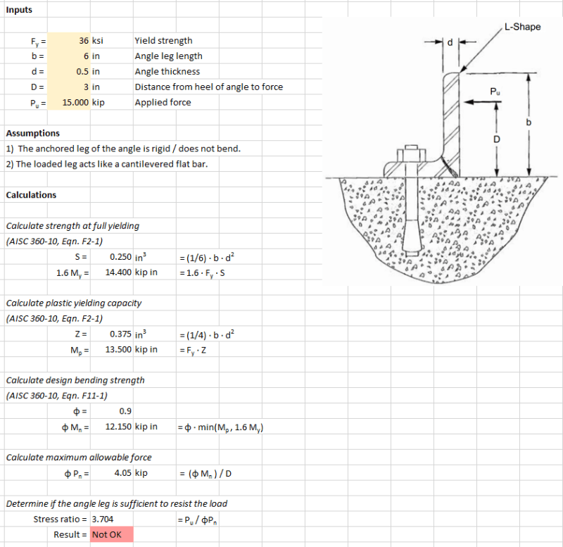
I needed to evaluated the capacity of an angle with a concentrated load.
Angle-loaded_fmnnvu.png

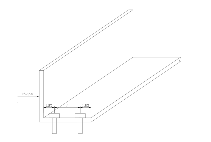
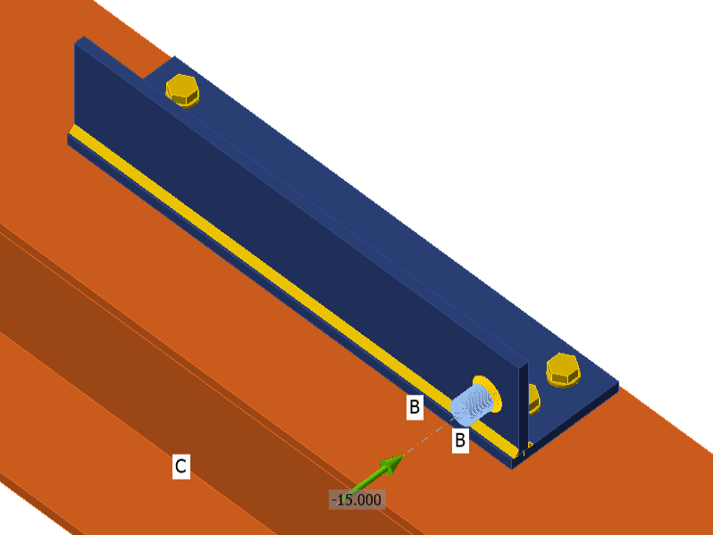
Bolts are in pairs each 12 inches and load can be either aligned with bolts, between bolts or any other position, but always in the same direction and high (3")
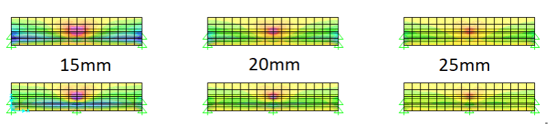
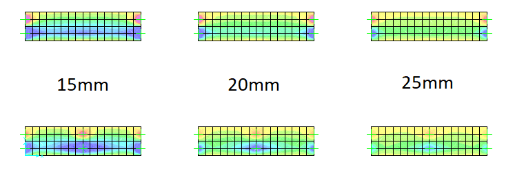
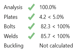
The proposed angle is L6x6x1/2, but I have modeled it as areas in SAP2000 and stresses are higher than Fy/1.67 for bending.
Is the thickness not enough? How can I evaluate it better?
 
Replies continue below

Recommended for you

CrabbyT thanks for the reference.
I can see in that thread (is closed :( ) that in the first case, the 15in length is assumed without any clarification.
The PE exam example is different because the load is distributed in the 6-in length so load is uniform.
Now in my case, load is concentrated and the problem is the width for the effect of load is not easy to define.
Look these images, I have limited stresses to Fy/1.67
Local_effects_nq46ya.png

Bending_Effects_lxvcvv.png

1/ first is the loaded side of the angle, the local effect are clear.
2/ second is the anchored side of the angle, the bending overstresses is clear too.
3/ Up are with the load bearing between anchored points, down are with the load bearing directly on bolts.
I have tried with 20mm and 25mm of thickness instead of 15mm and the stresses looks controlled.
But it's that "looks good" that doesn't convince me, I would like something more technical.
 
Some general comments...
[ul]
[li]The fastener at the free edge is the one that's doing the work; the one near the heel is collecting dust. The close spacing of the fasteners compromises the connection capacity. The only reason for two fasteners is for high shear, and I've not encountered a connection of such ilk.[/li]
[li]The fastener should be attached as close as possible to the free edge to increase the moment arm.[/li]
[li]For strength of the angle, use the plastic section modulus, not the elastic one... you gain 50% in strength (using LRFD).[/li]
[/ul]

-----*****-----
So strange to see the singularity approaching while the entire planet is rapidly turning into a hellscape. -John Coates

-Dik
 
isn't the load shown putting tension on the heel bolt ?

the FEM pictures are showing the stress in the web ? the "punching" shear ? I think this is a problem (in FEM) of a point load. If you applied the load over a small area it'd probably disappear.

"Hoffen wir mal, dass alles gut geht !"
General Paulus, Nov 1942, outside Stalingrad after the launch of Operation Uranus.
 
isn't the load shown putting tension on the heel bolt ?

My error... similar comments except the fastener at the heel stays and the other removed, with minimum distance to the heel.

-----*****-----
So strange to see the singularity approaching while the entire planet is rapidly turning into a hellscape. -John Coates

-Dik
 
Thousands of these type of angle clips for aircraft have been analyzed by hand using a 45 degree angle assumption from the load point to determine the effective width at the base if the angle. Then check bending at the base of the angle, fastener tension, and pull thru of the fastener in tension.

There is no reason to bludgeon this with a FEM and get a bunch of confusing stress fields.
 
I forgot I made a spreadsheet based on the problem from the link I posted above. 15 kips on the leg of an angle is a really tall order, and I don't think it'll work.

Regarding the point you made about the angle in that problem being 15" long - I don't think you scrolled down far enough in that thread.

Calc_w59qwb.png
 
SWComposites,
Thank you I will try that approach.
I think that is similar to yield lines approach?
I though that two bolts are better to control the eccentricity.
I don't think that using plastic properties be ok for bending stresses.
 
In aerospace we use plastic bending analysis all the time for metal parts. I'm not familiar with civil structures code requirements.

Two bolts are good if the load is at all reversible. If the load is always bending the angle inward, the outer bolt is not really needed unless one bolt is insufficient for shear (in which case just make the bolt larger).
 
X4vier:
What is your actual condition, is the anchored leg of the angle in continuous bearing? If so your model is not accurate, if not then CrabbyT's spreadsheet will not be applicable.
 
X4vier said:
There are two bolts each 12 inches.
OK, what are the two bolts attached to? Is there air in the 12 inches between bolts or solid material, if solid material is the angle leg tight to this material?

Your FEM model is resisting your applied load via tension and compression in the bolts, if there is concrete backup material and the angle leg rests on this concrete then the compression will be resisted by leg bearing not by a lone anchor (especially since as shown in your original post there is no mechanism to transfer this compression into the bolt).

 
Yes, that is true, the angle is bearing on a 12mm steel plate, so the bearing leg will transfer compression to the plate.
I have used IDEA to try to model the angle and it passes the check with the 15mm thickness.
I think IDEA uses the 5% strain limits so it assumed no problem with part of the angle yielding.
Idea_model_hhqxui.png

Idea_Results_whwrlx.png

What do you think of this approach?
 
CrabbyT said:
I forgot I made a spreadsheet based on the problem from the link I posted above. 15 kips on the leg of an angle is a really tall order, and I don't think it'll work.

Should the b for the section modulus not be the width (into the page) of the angle? Is section modulus not calculated based on the cross section of the shape in question (rectangular leg of the angle)?
 
Yes, b is the effective width. How much would you take in B if the angle is continuous and the bolts are 12" O.C.
 
Status
Not open for further replies.
Back
Top