Continue to Site

Eng-Tips is the largest engineering community on the Internet

Intelligent Work Forums for Engineering Professionals

  • Congratulations Danlap on being selected by the Eng-Tips community for having the most helpful posts in the forums last week. Way to Go!

CMU Block Tank Wall?

Status
Not open for further replies.

psychedomination

Structural
Jan 21, 2016
118
Hi there,

I while ago I designed a cesspit for a client.

Where I am from these are very common for all houses/small buildings and typically they are around 6’ deep. The local building code allows these to be built as unreinforced CMU block walls. The walls are typically staggered 2” every other course to provide weep holes for the sewage to slowly seep out, along with an open bottom/foundation to allow natural seepage. However, from an engineering perspective, I can’t get the tank walls to work when it is that deep without reinforcement (although I guess it must work if they have been doing it that way for XXX years with no recorded failures). In that scenario, I am assuming the walls would be acting more as a gravity wall and not a cantilever type wall that can take bending.

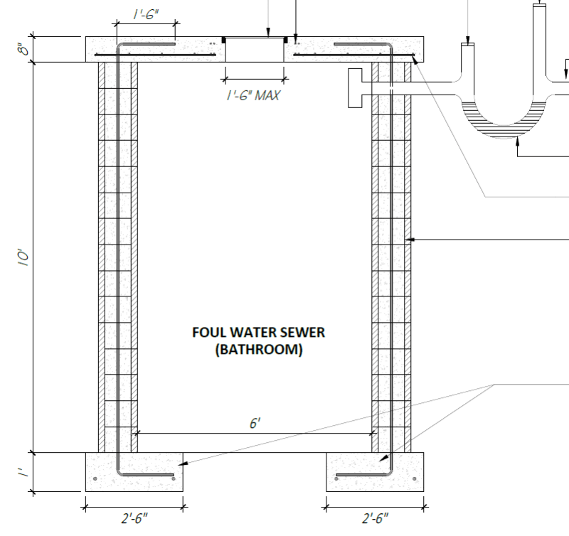
For my project, the cesspit was even deeper at 11’8” below grade. For the wall stem, I called for 16mm bars at 8” c/c in 12” filled CMU block. There isn’t a concern about large vehicles constantly going over the pit in the area but I thought it would make sense to allow for a small surcharge for construction equipment and material storage.

Cesspit_system_-_Copy_ctgdxt.png


Fast forward a few weeks, I got a call from the client stating that the contractor is asking why I specced 16mm @8” cc because they would like to put 12mm bars at 16” c/c.

I wasn’t too fussed by the comment and told them to stick with the original rebar that was called for. I wasn’t going to waste time/lose sleep on a few extra rebar in a tank that’s only 8’x6’ in plan area.

However, it does have me thinking about future projects if I can be less conservative and what is the best practice.

Although it’s a tank, when I was doing the design, I considered the wall as a propped cantilever retaining wall in the permanent state (propped after the top slab is poured) and as a cantilever retaining wall in the temporary state (in case the contractor backfilled prior to pouring the top slab). In all cases, I assumed the tank was empty.

Seeing as this is a tank, there will most likely be additional moment distribution to the tank wall corners that I didn’t consider. Is there any guidance that anyone can share regarding the design of CMU block tank wall design?

I do have the PCA ‘Rectangular Concrete Tanks’ document but would that be applicable for CMU block tank walls as well? The CMU walls don’t tend to have horizontal reinforcement.

Any advice/guidance would be greatly appreciated.
 
Replies continue below

Recommended for you

If you want the design to be leaner, you have to design it like a tank and introduce horizontal reinforcements. Your wall will span mostly horizontally. The tank is 8X6 (48 sq ft area), it would be a lot more efficient with the horizontal rebar design if it was 7X7 (49 sq ft).

 
With the small size in plan, your wall probably spans horizontally even though you reinforced it vertically. Maybe a trade off of vertical bars for a few horizontal/corner ones would be prudent.
 
Thanks for the responses so far! Understandable regarding the horizontal reinforcement. One of the issues with this is that they don’t manufacture or supply bond beam blocks in my location.

I’ve had this issue on previous projects as well.

As a fix for this I was looking to see if it was possible to include horizontal rebar in the mortar joints, however, this didn’t seem like it would work. 6mm bars seemed to be the max size that would work. That small diameter would not be suitable for most projects.

Alternatively, I was thinking of having the contractor put intermediate concrete bond beams where horizontal reinforcement was required but that’s probably cost prohibitive and if I do this may as well just do the whole wall in reinforced concrete.

Or I can have the contractor manually alter the whole CMU blocks to be bond beam blocks. However, this would be an additional cost as well.

In this case, I’m not sure which would be the best approach, including the horizontal rebar or stick with the additional vertical?

Thoughts?
 
General Note:
You could forget about steel rebars in this arrangement !!!
MCU are porose and will be 100% soaked with water soon or later {even with grouting or not}
you could ONLY depends on unreinforced MCU wall and resting on concrete floor
 
Use engineering judgment and add bond beam every few ft. Just modify the block. You just need a hammer to remove some of the side short walls and middle wall.
 
100% disagree with adn26. Concrete is also porous, but we still have rebar in below grade applications. It's all about proper detailing and protection - through cover, coatings, etc. Same goes for CMU. There are reinforced CMU walls below grade all over the place in damp locations and they work - if properly detailed and installed.

You may want to consider doing a 2 way analysis on the unreinforced arrangement. You'll end up with a 'plate' simply supported on all four sides with in-plane shear. Or make it a cylinder and use hoop stresses.
 
@ PhamEng
this is a septic tank, fully saturated chamber [from front and back [ponder]]
can't convinced that this detailing will work !
there are many factors overlooked here ..
 
adn26 - I'm well aware of what we're talking about. I'm also well aware of the pair of 45 year old, reinforced concrete septic tanks in my back yard (in a swamp, so also saturated on both sides) that are still performing well. Precast, reinforced septic tanks are more popular around here - by the time you take the safety precautions required by OSHA to put a mason in a 12' hole with 8' sides, the masonry costs twice as much - but that doesn't mean you can't protect a CMU wall adequately.
 
@adn26/phamENG, I'm not fully understanding, what is the issue with using reinforced CMU underground? Is the concern that underground water ingress will cause the rebar to corrode/sulphate attack on the concrete?

Reinforced CMU structures are used below grade in tons of scenarios where I am from (basement walls, water tanks, cesspits, manholes etc).

Regarding horizontal reinforcement or lack thereof. If the wall spans mainly in the horizontal direction and only vertical reinforcement is provided (suitable for the loads if the wall spans vertically). How would this act in reality if the CMU wall itself could not take these horizontal moments? Would the horizontal moments cause cracking in the corners, forcing the wall to then span vertically, which would then distribute the moments to the vertical rebar?
 
@ psychedomination
few weeks ago we had multistory building (above-ground) their columns rebars extremally damaged (corroded bar #25mm about 2mm)
concrete cover is expanded, and cracking distributed along whole column axes (this caused by dampness/moisture condensing)
- I don't questioning practice methods (but they should be modified)
- reinforcing rebars in sewage chamber is waste (structurally independent)
- wrote it as general note (not obligated)
 
In your case , the wall plates could be assumed horizontally supported from all edges. More over , the continuity of side walls will provide some fixity.

I do not have any idea for the applicable standards at your zone but it is worth to look to EC-6 ..


Suggest you to look to the following doc also..

Tim was so learned that he could name a
horse in nine languages: so ignorant that he bought a cow to ride on.
(BENJAMIN FRANKLIN )

 
@Adn26 I appreciate your input. I'm not sure how that correlates with CMU block though; you can have that issue with reinforced concrete as well. We use galvanized rebar in my area, and a suitable cover/admix to reduce water ingress (if necessary).

@HTURKAK, thanks for that document; it was very helpful. I'm not sure how familiar you are with the document but I do have a few questions hopefully someone can assist with:

1. It states that the flexural strength of masonry may not be used for walls subject to permanent loads (e.g. retaining walls). Is there another analysis approach that is used in situations with permanent loading? Would I use the arching lateral resistance analysis approach instead?

2. Table 2 only gives bending moment coefficient values for single leaf panels up to 250mm (10"). I'm using 12" blocks. What is done in that case?

3. For the calculations in that document, it incorporates an applied rectangular design load value per unit area (kPa). As this structure is underground, the load is triangular. Would the best approach for converting the triangular load to rectangular be to work out the max moment from the triangular load (assuming the wall panel is pinned on both ends vertically) and then use that max moment to calculate what the corresponding rectangular load value is with the max moment value?

I did run some quick calcs using the flexural strength of the masonry (assuming pinned top and bottom and restrained/continuous on the sides)and it seemed to pass in the unreinforced case, although I perhaps need to make amendments to the analysis based on my comments above.

Any guidance would be greatly appreciated. I've learned quite a bit already from this thread and the discussions/input will definitely help me for future projects as I refine my approach to these sorts of problems.
 
Mr. psychedomination (Structural)(OP)

The following docs. are LAW RESOURCE and you can download free of charge..

The short answer,
You may choose the lower bound value of the calculations ( moment coefficients, arching method and EN 1996-3 Simplified calculation method for basement walls )


Tim was so learned that he could name a
horse in nine languages: so ignorant that he bought a cow to ride on.
(BENJAMIN FRANKLIN )
 
Status
Not open for further replies.

Part and Inventory Search

Sponsor