Continue to Site

Eng-Tips is the largest engineering community on the Internet

Intelligent Work Forums for Engineering Professionals

  • Congratulations waross on being selected by the Eng-Tips community for having the most helpful posts in the forums last week. Way to Go!

Fishy punching shear results from FEM 2

Status
Not open for further replies.

milkshakelake

Structural
Jul 15, 2013
1,109
US
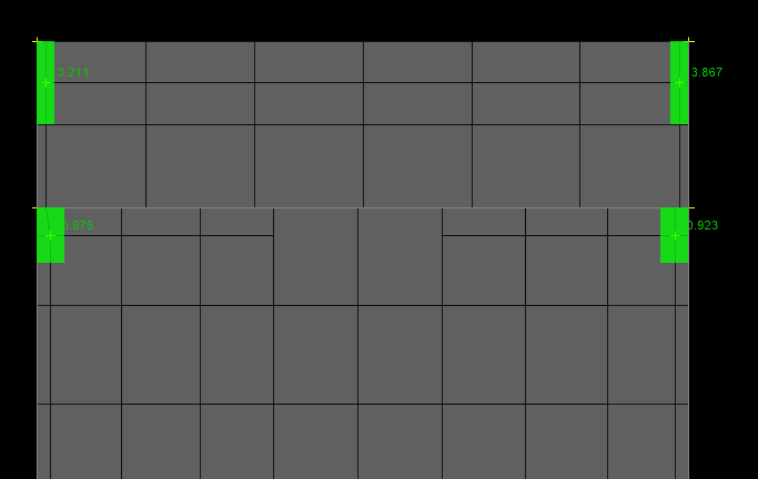
I have two 8x36 "wallumns" next to two 12x24 columns. The FEM results show a massive overstress in punching shear due to the minor axis moment.

Can I pin these columns to remove the moment? Normally, I don't do this because it's very unconservative for punching shear. But my engineering gut is telling me that these wallumns are almost like shear walls, where I do release the moment. So if it works for shear walls, it should work for this. Visually and intuitively, they're taking quite small loads. But I don't want it to actually punch through in real life, especially when the overstress is this high.

That being said, I'd also like to check this by hand. I think my go-to, the direct design method, is out the window because it doesn't meet the conditions. Can someone guide me in the right direction for doing a secondary check?

The other option is to just remove these columns, but I don't like it. It's a 6' cantilever with heavy SDL (concrete pavers).
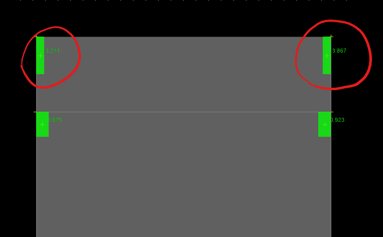
punching-shear-problem_bqoyxd.png
 
Replies continue below

Recommended for you

If the columns are modelled as point supports, a very big shear and bending moment can be the result of a singularity. Plate elements (shear deformable) don't combine well with point supports or sharp corners. Try modelling the connections with an area support and avoid applying point force or moment to the slab. This might fix the issue.

If this is some sort of punching shear check design module result, I can only recommend doing the hand-calculation to double check what the software spits out.

Regarding boundary conditions, they should reflect reality. If the columns and walls continue into the slab with rebar anchorage, the joints will develop moment.
 
What does the auto-mesh look like? I was having some very odd results in a model lately, and it turned out to be a mesh problem.
 
@EZBuilding I didn't run it in DECON yet, but it usually doesn't work when the ratio is 1.5 or more. I'll try it anyway. I'm using ETABS Ultimate and also tried it in SAFE with similar results.


@centondollar The software treats it as a line element instead of an area. I'll look into a way of getting it to act as an area, but I'm not sure it will make much difference compared to a point load. Will try anyway. As for hand calculation, I'll also give it a try. I'm just not 100% sure how to get the moment myself. I can use the FEM result for the moment.

As for the boundary conditions, it's true that it will develop a moment without having some kind of weird isolation joint. It's not really feasible to detail this joint without rebar. So I guess I have to keep it continuous instead of pinned.
 
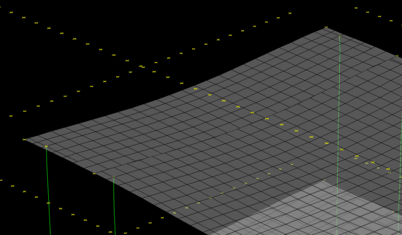
@Brad805 The mesh seems to be pretty reasonable.

mesh_ax8snx.png


Edit: I tried to use a general triangular mesh and got similar results, so it's not the mesh. But thanks for the tip. I'll keep that in mind if something weird comes up in the future.
 
Okay, the hand calculation still doesn't work out (didn't try stud rails). But using DECON to add stud rails works. I'll have to go in-depth to see how the program made it work, but this is a good solution. Thanks for the comments!
 
Is that your mesh? What size elements are we talking? Normally for concrete I don't let the elements get much bigger than 1' x 1' because the moments from out-of-plane forces will be underestimated. This could be a stress concentration....and with such large elements....very concentrated.
 
@WARose It was maximum 4'x4'. I changed it to 1'x1' (my computer didn't love this) but all my punching shear results went down a bit. Thanks for the tip! I resolved this already thanks to the other comments, but this is a great thing to remember.
 
I changed it to 1'x1' (my computer didn't love this) but all my punching shear results went down a bit.

Probably took a bit longer to run no doubt. If you were relying on this output for moment in the slab....you may want to take a second look at that too (as it has likely gone up assuming we are talking about uniform dead and live loads on this floor).
 
Those discontinuities were exactly what was causing my problems. I would try a different mesh option.
 
What’s the column load? How does the slab perform in one way shear?
 
Your mesh doesn’t appear that the interior slab is connected to the exterior? The exterior has nodes of it’s elements along the boundary of the interior slab mesh.
 
Also those proportions look pretty one way, if you just run the exterior bay in a 2D frame program do you get similar weak axis moment on the wallums? (Model the full frame columns and slab)
 
@WARose I didn't do the slab design yet, punching shear always comes first. But yeah, will design for these higher moments.

@Brad805 Yeah, even with a smaller mesh, it looks like there is a small amount of "tearing" in the 3D displacement. Will investigate further.
Screenshot_2023-01-18_113703_g0eora.png


@Tomfh The shear load is not high, 10.2 kips. That's a good idea; I didn't even think about designing this as a one way slab. It's really more like one way than two way.

@Celt83 It's connected but there are little tears in the displacement. I'll contact support about how to fix this. There's a general triangular mesh option where it doesn't tear, but I just don't like it (I'm not used to it, it's a new thing). I might have to go with that option. And yeah, I'll try the 2D frame program. I wish I knew how to do this by hand; I could've just checked the one way shear, but I'm not sure how to check it with a partially fixed support.
 
You have two 8x36 "wallumns" next to two 12x24 columns. But apparently (the picture in your last post ) These walumns modelled with line elements similar to the 12x24 columns..

I will suggest you to divide reasonably the minor axis moment and distribute to the three nodes, and assign pin for weak axis , rerun see the difference.


Tim was so learned that he could name a
horse in nine languages: so ignorant that he bought a cow to ride on.
(BENJAMIN FRANKLIN )

 
You have a fairly short backspan. How does the software assess the load on the column? Some of these FEM programs use tributary area logic, which can give very wrong results.
 
MSL,

A general commment on your FEM model - you're getting that tearing along the line b/w your "squat-er" wallumns and your narrow wallums b/c your plate nodes aren't connecting. Maybe your program has a super fancy element, but generally you'd want to get the corner nodes of all adjacent plate elements to be shared. Depending on how you want to handle it, you could end up with some triangle transition elements, some trapezoidal transition elements, or a very small mesh size across the model if you're determined to only have rectangular elements (all corners at 90 degrees).

Please note that is a "v" (as in Violin) not a "y".
 
What software is this? If what winelandwv said is true ("tearing" due to incorrect mesh, i.e., nodes of plate elements ending up "in the air" although the intention is to model a continuous plate), it doesn't exactly inspire confidence in the results.
 
MSL said:
The other option is to just remove these columns, but I don't like it. It's a 6' cantilever with heavy SDL (concrete pavers).

In most cases, that is precisely what I would do. Redundant, vertical support that close together often causes detailing and analysis awkwardness like this.

MSL said:
But my engineering gut is telling me that these wallumns are almost like shear walls, where I do release the moment. So if it works for shear walls, it should work for this.

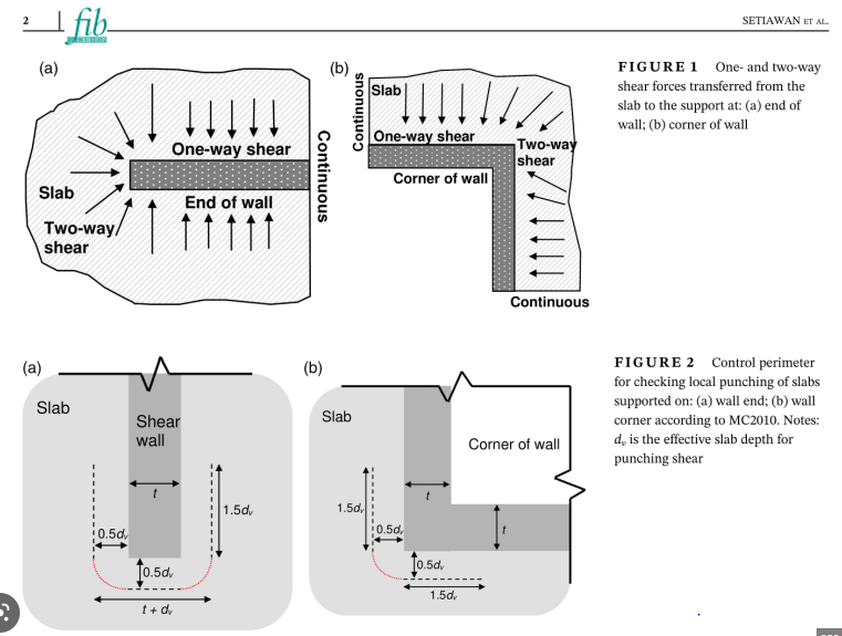
I agree, and a lot of folks do that successfully. Moreover, with a support of these proportions at an edge condition, I don't feel that two way punching shear provisions are all that relevant anyhow. And ACI's latest reflects this sentiment in that your allowable punching stress will likely wind up being, effectively, one way shear just as tomfh mentioned.

When it comes to this kind of stuff, I feel that Eurocode has been leading the way as per the diagram below. In accordance with that, I'd be inclined to check one way shear over an L-shaped section proportioned like Eurocode does it.

MSL said:
But I don't want it to actually punch through in real life, especially when the overstress is this high.

My approach would be this:

1) Accept that this will be rough stuff unlikely to be fully captured accurately by any production FEM model.

2) Throw in that pin as you said.

3) Provide copious "detailing" top steel coming off of the wall perpendicularly.

4) Have well anchored bottom steel running into the wall perpendicularly.

5) Run some healthy top steel and integrity steel over the wall and near it, parallel to the wall.

With all of that, you should have both reasonable crack control and a safe design.

C01_bfryae.png
 
Status
Not open for further replies.

Part and Inventory Search

Sponsor